Universal Serial Bus (USB)
is a high-speed wired communication standard used to connect peripheral devices (keyboard, mouse, printer, flash drive) to a computer or other electronic devices.
- Developed in: 1995
- By: Intel, Microsoft, IBM, and other tech companies
1. Key Features
| Feature | Description |
|---|---|
| Host Controller | Hardware + software in PC to control USB |
| Master-Slave Protocol | Host controls all communication |
| Expandable | Multiple devices can be connected via hubs |
| Plug & Play | No manual configuration needed |
2. USB Power Delivery (USB PD)
USB PD is a technology that allows higher power to be delivered through a USB cable. It also supports bi-directional power flow – power can go both ways between devices.
How USB Detects a Device
- A device must pull D+ or D– HIGH to 3.3V using a pull-up resistor
- This tells the host/hub that a device is connected
- No pull-up resistor → USB assumes nothing is connected
Pull up registor
┌─────────────────────────────┐
│       USB Controller Chip    │
│  ┌─────────────────────┐    │
│  │  Pull-up Resistor   │    │
│  │  (1.5 kΩ)           │    │
│  └─────────────────────┘    │
│         │                    │
│    ┌────┴────┐              │
│    │         │              │
│   D+        D-              │
└─────────────────────────────┘
         │         │
         ▼         ▼
    Connected to Host via USB Cable
User plugs in device
        ↓
Device gets +5V power
        ↓
Pull-up resistor that build in USB pulls D+ or D– HIGH (3.3V)
        ↓
Host checks D+ / D– lines
        ↓
   ┌────┴────┐
   │         │
 D+ HIGH   D– HIGH   → Low Speed Device
 (Full/Hi-Speed)
   │         │
   └────┬────┘
        ↓
Host sends Reset (D+ & D– LOW for 10ms)
        ↓
Device is ready to communicate
3 Examples of USB
3.1 Example 1: Charging Low-Power Peripherals
| Item | Details |
|---|---|
| Connection | Laptop connected to AC adapter + Speaker connected to laptop via USB |
| What Happens | Laptop provides power to the speaker through the USB port |
| Use Case | Charging or powering small devices like speakers, headphones, smartphones |
Simple: Laptop acts as a power source for small devices.
3.2 Example 2: Docking Station Power Delivery
| Item | Details |
|---|---|
| Connection | AC adapter connected to Docking Station → Docking Station to Laptop via single USB-C cable |
| What Happens | Docking Station provides power AND data to the laptop through one cable |
| Use Case | No separate charger needed for laptop – all through one USB-C cable |
Simple: One cable from docking station charges the laptop and connects all peripherals.
3.3 Example 3: Powering High-Draw External Storage
| Item | Details |
|---|---|
| Connection | Laptop on AC power + External HDD/SSD connected via USB-C |
| What Happens | Laptop provides enough power to run the external drive |
| Use Case | High-power devices like NVMe enclosures or external hard drives run without separate power adapters |
Simple: USB-C provides enough power to run external hard drives – no extra plug needed.
3.4 Example 4: Bi-Directional Monitor Charging & Display
| Item | Details |
|---|---|
| Connection | Monitor connected to wall outlet + Laptop connected to Monitor via single USB-C cable |
| What Happens | One cable does TWO things: |
| 1. Video data from laptop → Monitor (display) | |
| 2. Power from Monitor → Laptop (charges laptop) | |
| Use Case | Monitor charges laptop while showing the display – no separate charger needed |
3.5 USB On-the-Go (OTG)
Normal: Computer is the host – you connect mouse, keyboard, pen drive to it.
With OTG: Your smartphone or tablet becomes the host!
How it works:
- Use an OTG adapter to connect pen drives, keyboard, mouse, or even a 3D scanner directly to your phone
- Your phone can read files from the pen drive
- Your phone can also act like a pen drive when connected to a computer
Examples:
- Phone + USB mouse = Desktop-like experience
- Phone + Pen drive = Copy files directly
3.5 Advantages
| Advantage | Description |
|---|---|
| Single Interface | One port connects many devices |
| Auto Configuration | No DIP switches or IRQ settings needed |
| Hot-Plugging | Connect/disconnect while computer is ON |
| Low Cost | Cheap to produce and use |
| Power Supply | Provides power to devices (no extra adapter needed) |
| High Speed | USB 3.0: 5 Gbps, USB4: 40 Gbps |
Limitations
| Limitation | Description |
|---|---|
| Speed | Slower than Gigabit Ethernet |
| No Peer-to-Peer | Two hosts or two peripherals cannot talk directly |
| Distance | Max cable length: 5 meters (USB 2.0) |
| No Broadcasting | Only host-to-peripheral messages, no broadcast |
USB Versions & Speeds
| Version | Max Speed | Name |
|---|---|---|
| USB 1.0 | 1.5 / 12 Mbps | Low/Full-Speed |
| USB 2.0 | 480 Mbps | Hi-Speed |
| USB 3.0 | 5 Gbps | SuperSpeed |
| USB 3.1 | 10 Gbps | SuperSpeed+ |
| USB 3.2 | 20 Gbps | SuperSpeed+ |
| USB4 | 40 Gbps | USB4 |
Cable Length Limits
| Version | Max Length |
|---|---|
| USB 1.0/1.1 | 3 meters |
| USB 2.0 | 5 meters |
| USB 3.0 | 3 meters |
For longer distances, USB hubs are needed.
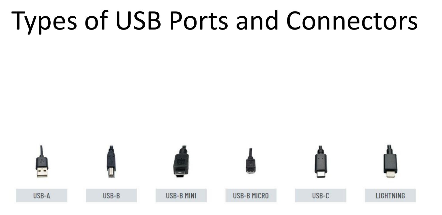
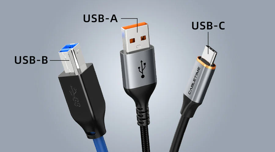
USB Connector Types
| Connector | Shape | Used In |
|---|---|---|
| Type-A | Rectangular | Computers, chargers |
| Type-B | Square | Printers, scanners |
| Type-C | Oval, reversible | Modern phones, laptops |
| Micro-USB | Small, flat | Old phones, tablets |
| Mini-USB | Small, old | Old cameras, MP3 players |
USB Connector Pinouts
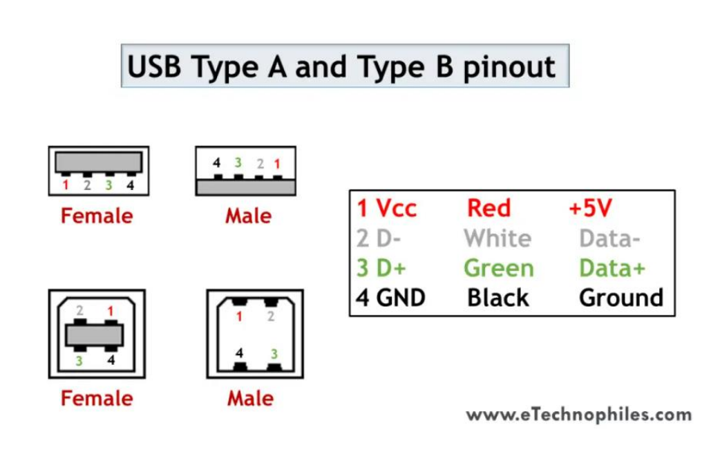
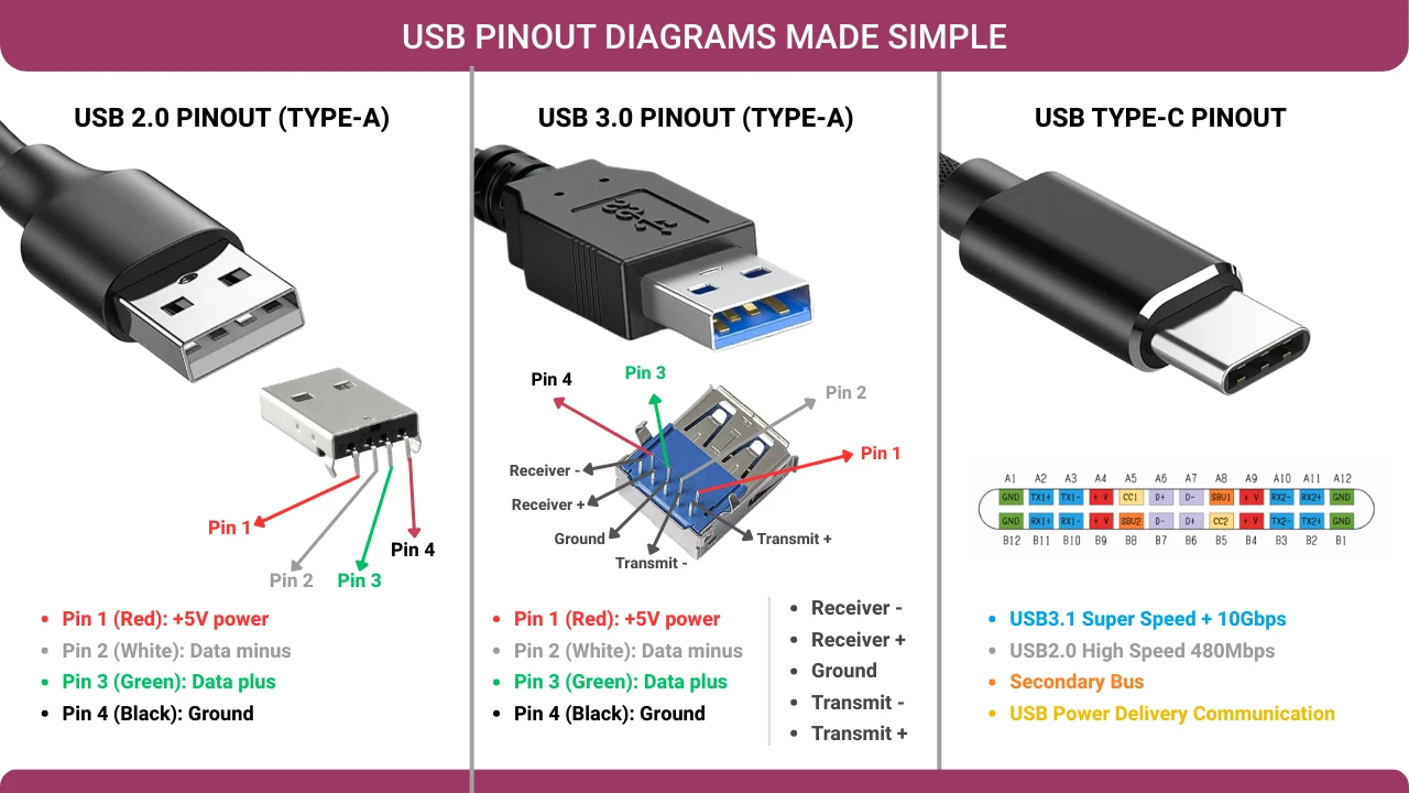
1. USB Type A and Type B (4 Pins) USB 2.0
Type A: Flat port (computers, pen drives)
Type B: Square port (printers, scanners)
| Pin | Signal | Wire Color | Function |
|---|---|---|---|
| 1 | Vcc | Red | +5V Power |
| 2 | D– | White | Data Negative |
| 3 | D+ | Green | Data Positive |
| 4 | GND | Black | Ground |
1.2. Key Points
USB uses 4 shielded wires:
- 2 for power (+5V and GND)
- 2 for differential data (D+ and D–)
D+ and D– work together (not separate connections)
Twisted pair used to reduce noise
Half-duplex – data flows in one direction at a time
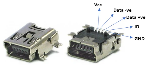
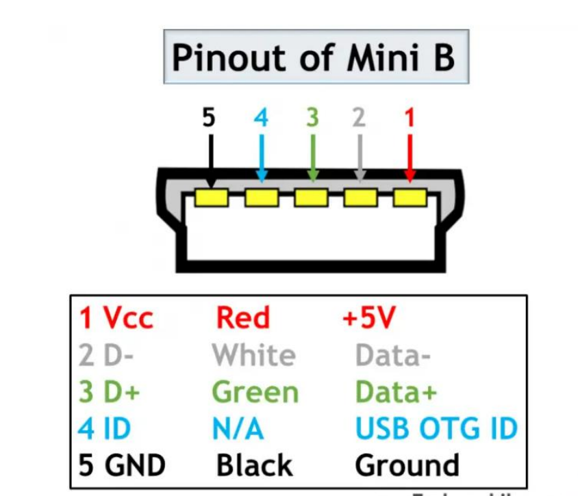
2. Mini B Pinout (5 Pins) USB 2.0
Used in: Old phones, MP3 players, portable hard drives, digital cameras
| Pin | Signal | Wire Color | Function |
|---|---|---|---|
| 1 | Vcc | Red | +5V Power |
| 2 | D– | White | Data Negative |
| 3 | D+ | Green | Data Positive |
| 4 | ID | N/A | OTG ID – tells device if it is Host or Peripheral |
| 5 | GND | Black | Ground |
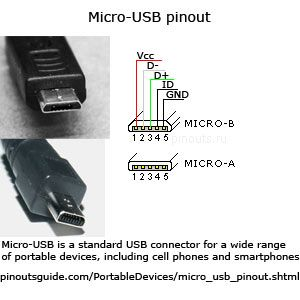
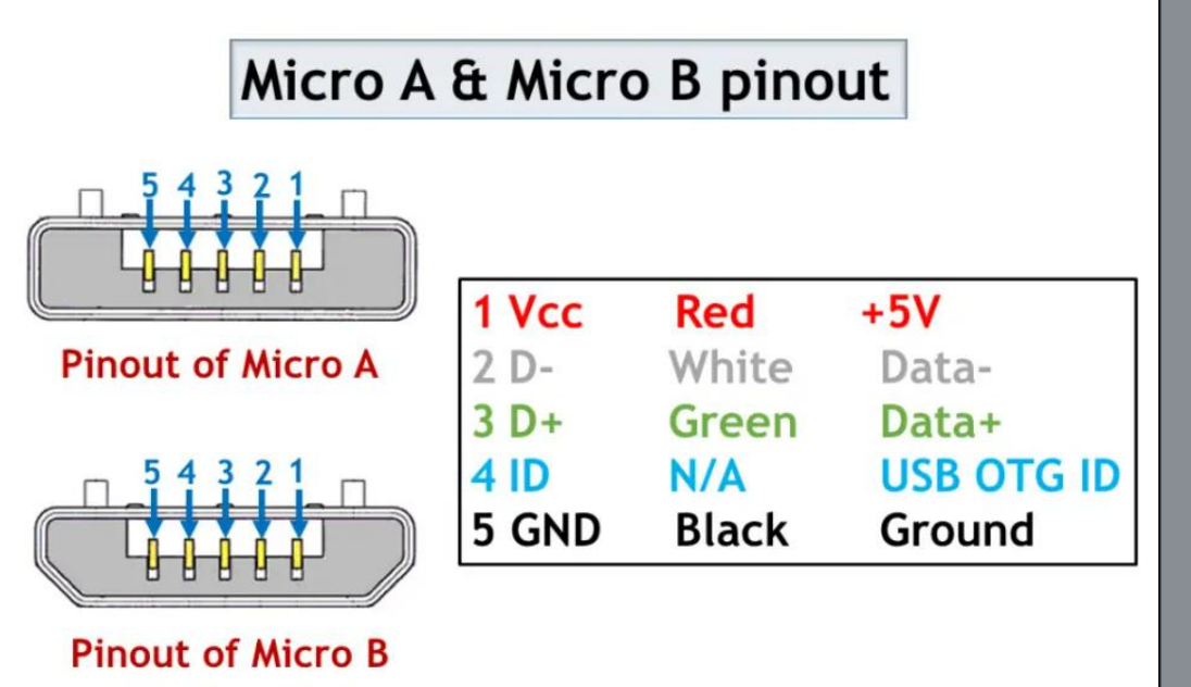
3. Micro A & Micro B Pinout (5 Pins) USB 2.0
Micro B: Used in most Android phones before USB-C
Micro A: Completely rectangular shape
| Pin | Signal | Wire Color | Function |
|---|---|---|---|
| 1 | Vcc | Red | +5V Power |
| 2 | D– | White | Data Negative |
| 3 | D+ | Green | Data Positive |
| 4 | ID | N/A | OTG ID – enables Host mode |
| 5 | GND | Black | Ground |
4. Type A and B USB 3.0
USB 3.0 (SuperSpeed) is the third generation of USB. It is 10 times faster than USB 2.0.
4.1 USB 2.0 vs USB 3.0 – Key Difference
| Feature | USB 2.0 | USB 3.0 (SuperSpeed) |
|---|---|---|
| Data Flow | Half-Duplex (one way at a time) | Full-Duplex (both ways at once) |
| Speed | 480 Mbps | 5 Gbps (10x faster) |
| Pins | 4 | 9 |
| Separate TX/RX | No | Yes (Transmit + Receive lines) |
4.2 Why 9 Pins?
USB 3.0 is backward compatible – it works with USB 2.0 devices too.
| Part | Pins | Purpose |
|---|---|---|
| Front / Top | 4 pins | USB 2.0 (Power, Data+, Data–, Ground) |
| Back / Bottom | 5 pins | SuperSpeed (Transmit, Receive, Ground) |
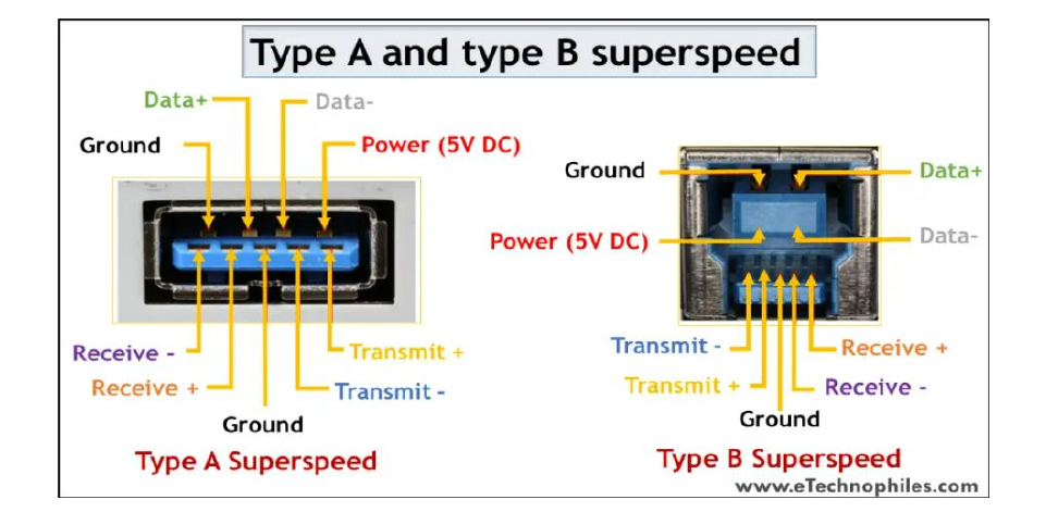
4.3 Type A SuperSpeed (Blue Flat Port)
Top 4 Pins (USB 2.0):
| Pin | Signal | Function |
|---|---|---|
| 1 | VCC | +5V Power |
| 2 | D– | Data Negative |
| 3 | D+ | Data Positive |
| 4 | GND | Ground |
Bottom 5 Pins (SuperSpeed):
| Pin | Signal | Function |
|---|---|---|
| 5 | SSRX– | Receive Negative |
| 6 | SSRX+ | Receive Positive |
| 7 | GND_DRAIN | Signal Ground |
| 8 | SSTX– | Transmit Negative |
| 9 | SSTX+ | Transmit Positive |
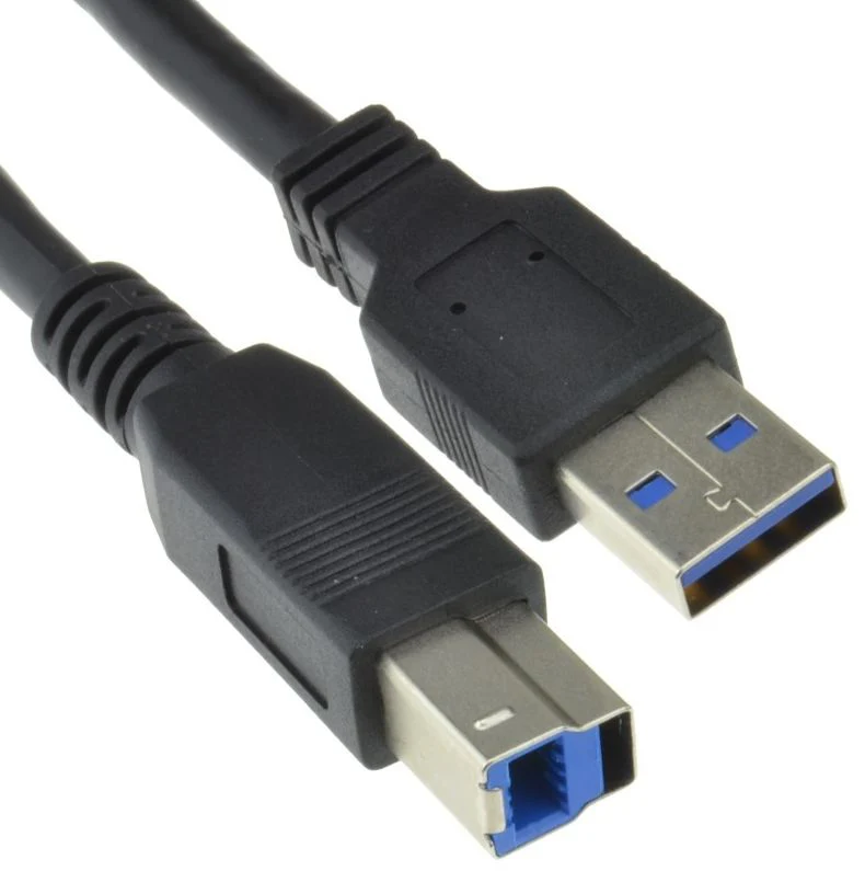
4.4 Type B SuperSpeed
Used in: External hard drives, high-speed printers, drive enclosures
Top Part (USB 2.0):
- 4 pins: Power, Data+, Data–, Ground
Bottom Extra Part (SuperSpeed):
- 5 pins: Transmit (+/–), Receive (+/–), Ground
Shape: Looks like USB 2.0 Type-B but taller (has extra bump on top)
4.4 USB 3.0 Micro-B
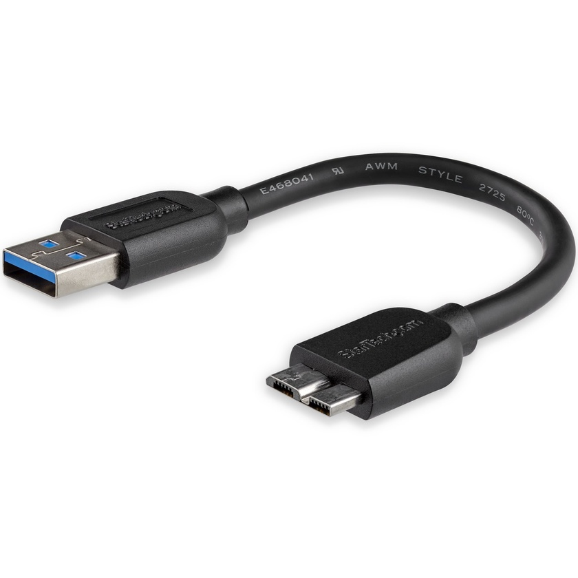
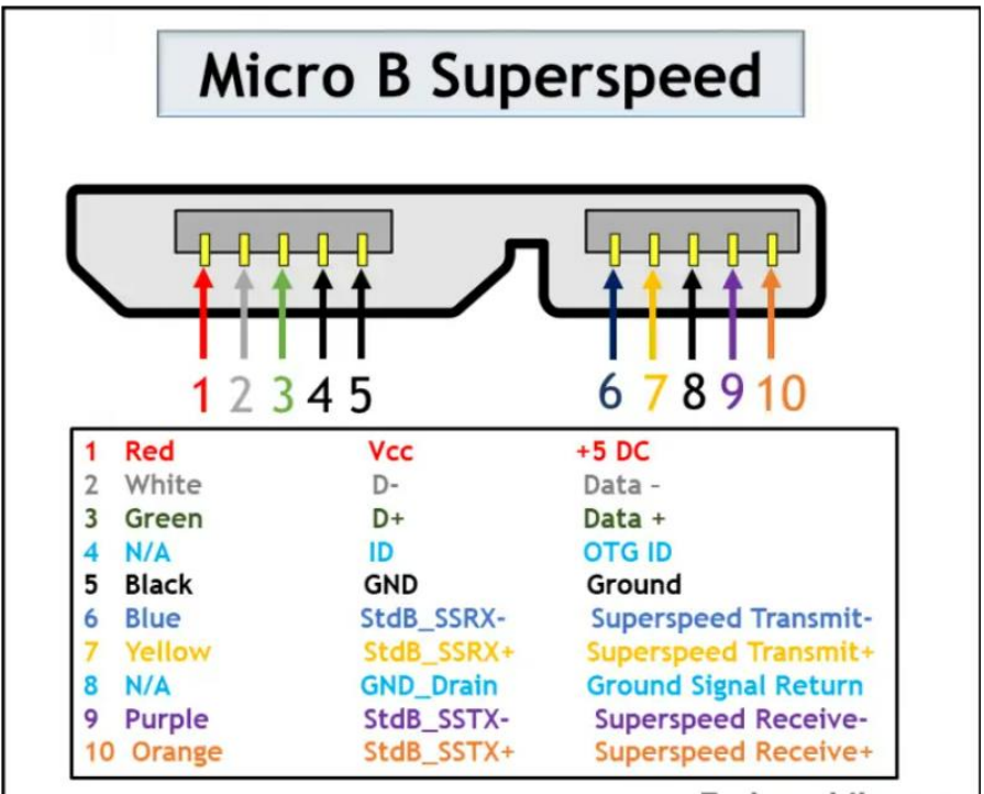
Why is it Wider?
USB 2.0 Micro-B had only 5 pins. For SuperSpeed, 5 extra pins were needed. So the connector was made wider to fit them.
USB 2.0 Micro-B:     ████████ (Narrow)
USB 3.0 Micro-B:     ████████████ (Wider, two-part)
Pinout (10 Pins)
| Pin | Signal | Function |
|---|---|---|
| 1 | VCC | +5V Power |
| 2 | D– | USB 2.0 Data Negative |
| 3 | D+ | USB 2.0 Data Positive |
| 4 | ID | OTG Detection |
| 5 | GND | Ground (USB 2.0) |
| 6 | SSTX– | SuperSpeed Transmit Negative |
| 7 | SSTX+ | SuperSpeed Transmit Positive |
| 8 | GND_DRAIN | Signal Ground |
| 9 | SSRX– | SuperSpeed Receive Negative |
| 10 | SSRX+ | SuperSpeed Receive Positive |
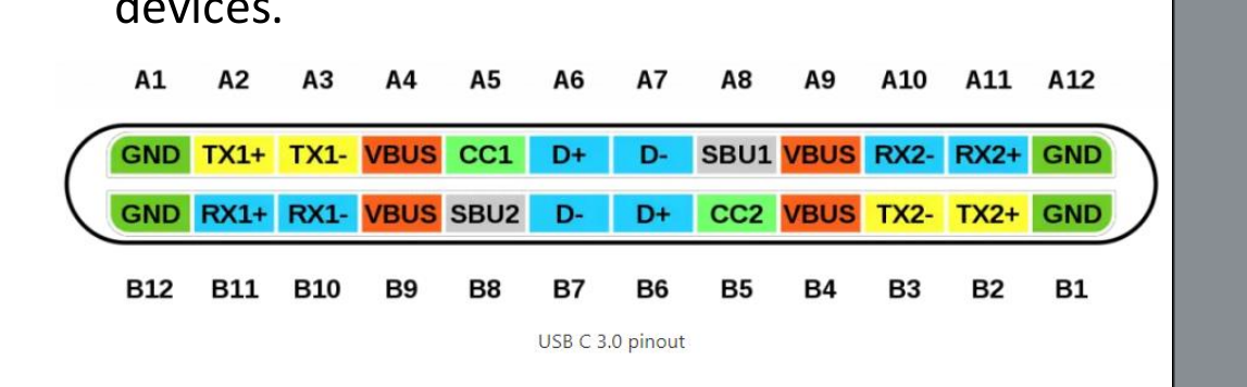
4.5 USB Type-C 3.0
Flippable (Reversible) Design
Biggest advantage: You can plug it in any way – upside down or right side up – it works!
| Old USB Type-A | USB Type-C |
|---|---|
| One direction only | Any direction |
| Can damage port if forced | Completely safe |
| Annoying to use | Easy and convenient |
5. USB4 Architecture
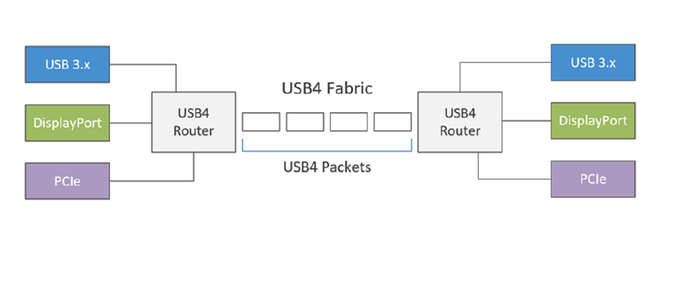
Three Layers of USB4
┌─────────────────────────────────┐
│     Application Layer           │
│  (Protocol Tunneling & Routing) │
└───────────────┬─────────────────┘
                │
┌───────────────▼─────────────────┐
│     Protocol Layer              │
│  (Packet Creation & Exchange)   │
└───────────────┬─────────────────┘
                │
┌───────────────▼─────────────────┐
│     Physical Layer              │
│  (Data Transmission)            │
└───────────────┬─────────────────┘
                │
    ┌───────────┼───────────┐
    │           │           │
┌───▼───┐ ┌───▼───┐ ┌───▼───┐
│USB 3.x│ │Display│ │ PCIe  │
│ Data  │ │ Port  │ │ Data  │
└───────┘ └───────┘ └───────┘
Layer 1: Application Layer
| Function | Description |
|---|---|
| Protocol Tunneling | Carries USB 3.x, DisplayPort, and PCIe data together |
| Routing | Sends data to the correct destination |
Layer 2: Protocol Layer
| Function | Description |
|---|---|
| Packet Creation | Creates data packets to send |
| Packet Exchange | Manages sending and receiving of packets |
Layer 3: Physical Layer
| Function | Description |
|---|---|
| Data Transmission | Actually sends data through the cable |
5.1 What Flows Through USB4?
USB4 can carry three types of data at the same time:
| Protocol | Carries |
|---|---|
| USB 3.x | Regular data (files, etc.) |
| DisplayPort | Video signals (to monitors) |
| PCIe | High-speed data (to external GPU, SSD) |
5.2 USB4 – Questions and Answers
Q1: What is Protocol Tunneling?
Answer: When devices communicate, they use a protocol. Protocol Tunneling creates a “pipe” using one protocol and sends data of another protocol through it.
USB4 Protocol Tunneling: Creates a USB-C tunnel to send DisplayPort or PCIe data. It is similar to Alt Mode but does not require a separate DP or PCIe controller.
Q2: What is USB4 Fabric?
Answer: The word “fabric” describes a network of interconnected nodes (like switches). When drawn, the crisscross pattern looks like woven cloth.
USB4 Fabric: Dynamically manages connections between USB4 routers so multiple protocols can share resources at the same time.
Q3: Will Apple Support USB4?
Answer: Yes. Apple’s new MacBooks and Mac Mini with Apple Silicon (M1, M2, M3) support both USB4 and Thunderbolt 3.
6. USB Architecture
6.1. Does USB-C Support USB 2.0?
| Question | Answer |
|---|---|
| What is USB-C? | A physical connector shape (not a speed standard) |
| Can USB-C support USB 2.0? | YES – Many cheap USB-C cables only give 480 Mbps (USB 2.0 speed) |
| Can USB-C do video? | Only if the cable supports Alt Mode or higher speed |
Key Point: USB-C is just the plug shape. The speed depends on the technology inside!
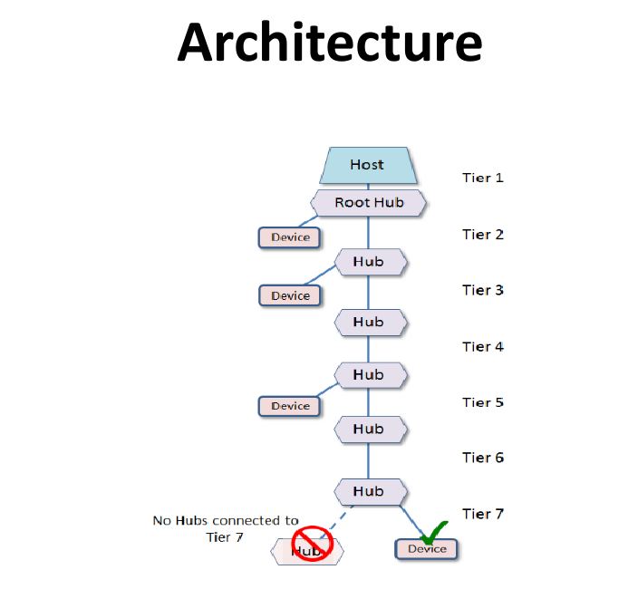
6.2. USB Architecture – Tiered-Star Topology
| Component | Role |
|---|---|
| Host | Only one host (computer) – controls everything |
| Root Hub | Built into the host – gives USB ports |
| Function | Devices like mouse, printer, scanner |
6.3. Upstream & Downstream Connections
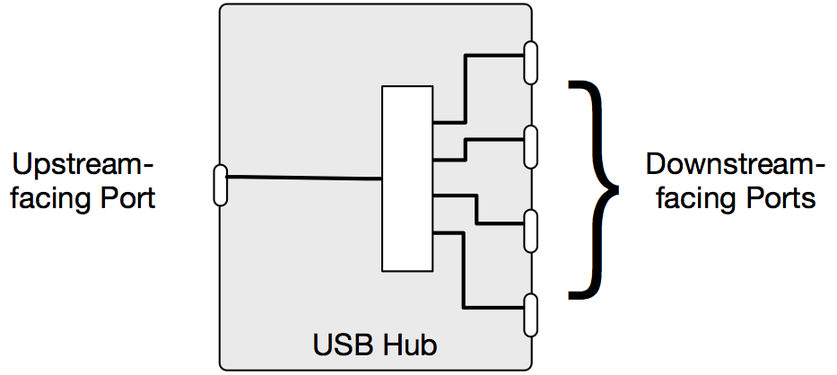
| Connection | Purpose |
|---|---|
| Upstream | Connects up to the host or higher hub (only 1 per hub) |
| Downstream | Connects down to devices or lower hubs (up to 7 per hub) |
7. USB Host Controllers and Endpoints
7.1. Host Controllers
Host controllers are the hardware inside your computer that manage USB communication. A software layer called HCD (Host Controller Device) helps the OS talk to this hardware.
Types of Host Controllers:
1. OHCI (Open Host Controller Interface)
| Feature | Details |
|---|---|
| Made by | Compaq, Microsoft, National Semiconductor |
| For | USB 1.0 and USB 1.1 |
| Speed | Low Speed and Full Speed |
| Type | Hardware-oriented (does more work in hardware, less CPU load) |
2. UHCI (Universal Host Controller Interface)
| Feature | Details |
|---|---|
| Made by | Intel |
| For | USB 1.0 and USB 1.1 |
| Speed | Low Speed and Full Speed |
| Type | Software-oriented (needs license from Intel, uses more CPU) |
3. EHCI (Extended Host Controller Interface)
| Feature | Details |
|---|---|
| Made by | USB-IF (all companies together) |
| For | USB 2.0 (High Speed) |
| Speed | Handles High Speed itself |
| Special | Passes Low/Full Speed to OHCI or UHCI (companion controllers) |
4. VHCI (Virtual Host Controller Interface)
| Feature | Details |
|---|---|
| What is it? | Not real hardware – a virtual controller |
| Use | Shows virtual USB devices not physically connected |
| Example | On Linux, used to access USB devices from other computers via USB/IP protocol |
5. USB4 Host Interface
| Feature | Details |
|---|---|
| What is it? | Latest and most advanced host interface |
| Manages | USB, DisplayPort, PCI Express, Thunderbolt, and Host-to-Host communication |
| Benefit | One system handles everything together |
7.2. Endpoints
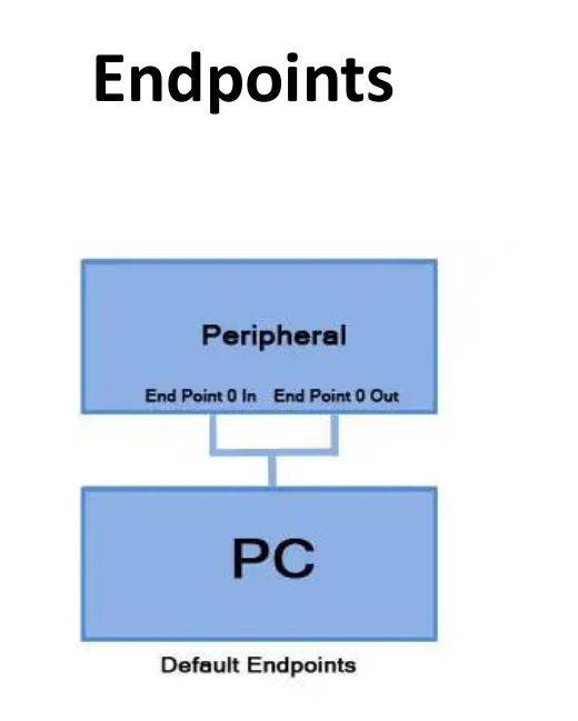
Endpoints are small memory buffers (storage areas) inside a USB device where data is temporarily stored.
7.2.3 Key Points:
| Feature | Explanation |
|---|---|
| Direction | Same endpoint number can have IN (host receives) and OUT (host sends) directions |
| IN / OUT | Always from host’s perspective |
| Endpoint 0 | The default endpoint – always active when a device is first plugged in |
7.2.4 Endpoint 0 – The First Contact
| Step | What Happens |
|---|---|
| 1. Plug in | Device connected to computer |
| 2. Endpoint 0 active | Only this endpoint works at first |
| 3. Enumeration | Host asks: “Who are you? What is your name, brand, type?” |
| 4. Identity confirmed | Host learns about the device |
| 5. Other endpoints open | Now endpoints like 1, 2, etc. become active for data transfer |
7.2.5 Example: USB Printer
| Endpoint | Direction | Purpose |
|---|---|---|
| Endpoint 0 | IN / OUT | Enumeration (initial setup) |
| Endpoint 1 | OUT | Host sends print data to printer |
| Endpoint 2 | IN | Printer sends status (ink level, paper jam) back to host |
8. USB Pipes
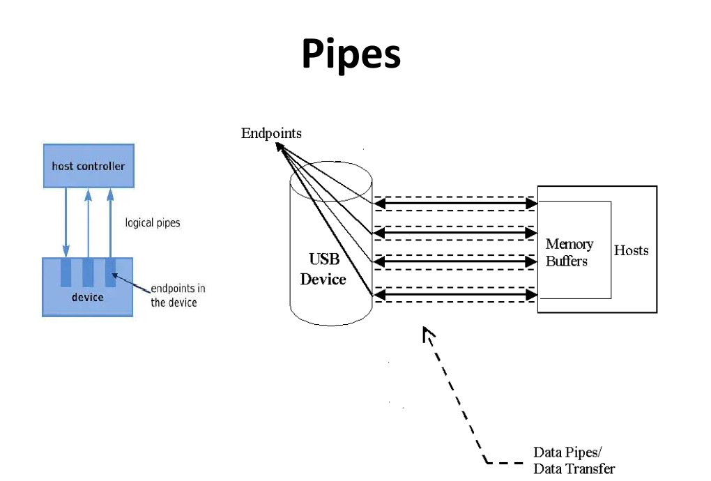
is a logical (software) connection between the host (computer) and an endpoint (memory buffer inside a USB device).
Simple Analogy:
- Endpoint = water tank (memory in device)
- Host = main water source (computer)
- Pipe = the pipe that carries water from source to tank
Pipes are created automatically when you plug in a device and destroyed when you unplug it.
8.1 Types of Pipes
1. Message Pipes
| Feature | Description |
|---|---|
| Direction | Bi-directional (data can go both ways) |
| Format | Must follow defined packet format (strict rules) |
| Use | Control Transfer – used for settings, commands, identification |
| Control | Fully controlled by the host (computer) |
Example: When you plug in a new device, the host uses a message pipe to ask: “Who are you? What is your name?”
2. Stream Pipes
| Feature | Description |
|---|---|
| Direction | Unidirectional (one way only) |
| Format | No fixed format – can carry raw data |
| Use | Large data transfer |
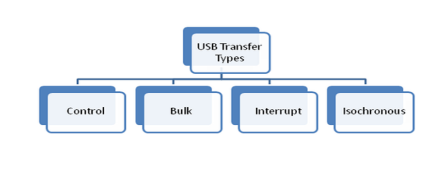
Four Types of Transfers Supported by the USB
| Transfer Type | Used For | Example |
|---|---|---|
| Bulk | Large data, reliable | Copying files to pen drive |
| Interrupt | Small data, frequent | Mouse movement, keyboard press |
| Isochronous | Real-time data | Webcam video, USB speaker audio |
8.2 The Default Control Pipe
| Feature | Description |
|---|---|
| What is it? | A special message pipe connected to Endpoint 0 |
| Direction | Bi-directional (uses Endpoint 0-IN and Endpoint 0-OUT) |
| Purpose | Enumeration – identifies the device when first plugged in |
| Always Active | Every USB device has this pipe |
9. USB Transactions, Packets, and Handshaking
1. What is a USB Transaction?
A USB transaction is one complete communication between the host and a device. Each transaction has up to 3 packets:
| Step | Packet Type | Sent By | Purpose |
|---|---|---|---|
| 1 | Token Packet | Host (always) | Starts the transaction – tells which device and endpoint |
| 2 | Data Packet | Host or Device | Carries the actual data |
| 3 | Handshake Packet | Host or Device | Confirms if data was received successfully |
2. USB Packet Fields (Structure)
Every USB packet contains these parts:
| Field | Size | Purpose |
|---|---|---|
| Sync | 8-bit (Low/Full) / 32-bit (High) | Synchronizes clocks between sender and receiver |
| PID | 8-bit (4-bit type + 4-bit complement) | Identifies packet type (Token, Data, Handshake) |
| ADDR | 7-bit | Address of the device (0 to 127) |
| ENDP | 4-bit | Endpoint number inside the device (0 to 15) |
| CRC Field (Cyclic Redundancy Check) | 5-bit (Token) / 16-bit (Data) | Error detection code |
| EOP Field (End of Packet) | Special signal | Marks the end of the packet |
3. Handshaking – Confirming Data Transfer
Handshaking ensures data is received correctly.
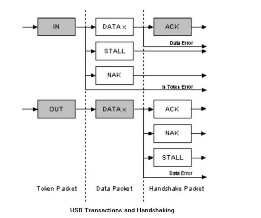
IN Transaction (Host reads data from device)
| Step | Packet | Sent By | Meaning |
|---|---|---|---|
| 1 | IN Token | Host | “Device, send me data” |
| 2 | DATA | Device | Device sends data |
| 3 | ACK | Host | “Data received correctly!” |
Other Responses:
| Response | Meaning |
|---|---|
| NAK | Device has no new data to send |
| STALL | Device has an error or doesn’t support the request |
OUT Transaction (Host writes data to device)
| Step | Packet | Sent By | Meaning |
|---|---|---|---|
| 1 | OUT Token | Host | “Device, I’m sending you data” |
| 2 | DATA | Host | Host sends data |
| 3 | ACK | Device | “Data received and stored correctly!” |
Other Responses:
| Response | Meaning |
|---|---|
| NAK | Device is busy (buffer full) – try again later |
| STALL | Device doesn’t support the command |
| NYET | “Not Yet” – device is busy, not ready for next packet |
9. USB Device States and Classes
1. USB Device States (6 Stages)
When you plug in a USB device, it goes through 6 states:
| State | What Happens |
|---|---|
| 1. Attached | Device is physically connected to the computer |
| 2. Powered | Device gets power from the host – but can only draw up to 100 mA initially |
| 3. Default | Device resets – uses address 0 and Endpoint 0 to start communication |
| 4. Addressed | Host assigns a unique address (1 to 127) to the device |
| 5. Configured | Host loads the correct driver – device is now ready to work |
| 6. Suspended | Power-saving mode – if bus is idle for 3 ms, device draws less than 500 µA |
Plug in → Attached → Powered → Default → Addressed → Configured → Working!
                                                              ↓
                                                         Suspended (idle)
2. USB Device Classes
USB uses Class Codes so the computer can use a generic driver for similar devices – no need for manufacturer-specific drivers.
Class codes are stored in the device’s Descriptor memory.
Common USB Device Classes
| Class Code | Device Class | Transfer Type | Examples |
|---|---|---|---|
01H | Audio | Isochronous | Speaker, Microphone, Sound Card |
03H | HID (Human Interface) | Interrupt | Keyboard, Mouse, Joystick |
07H | Printer | Bulk | Laser Printer, Inkjet Printer |
08H | Mass Storage | Bulk | Pen Drive, External HDD, Card Reader |
09H | USB Hub | Control / Interrupt | USB Hub (to add more ports) |
0Dh | Content Security | Bulk / Interrupt | Fingerprint Reader |
0Eh | Video | Isochronous / Bulk | Webcam, Scanner |
Device Plugged In
        ↓
Host reads Class Code from Descriptor(store in computer os)
        ↓
Host loads the matching generic driver
        ↓
Device is ready to use
10. USB Enumeration
Enumeration is the process where the computer (Host) identifies a newly connected USB device and prepares it for use. It happens automatically every time you plug in a device.
The 4 Steps of Enumeration
Step 1: Reset & Speed Detection
| Action | Details |
|---|---|
| Device plugged in | Hub detects the new device and informs the Host |
| Host sends Reset signal | Host resets the device |
| Speed detected | Host determines if device is Low Speed, Full Speed, or High Speed |
Step 2: Default Address & Descriptor Read
| Action | Details |
|---|---|
| Device enters Default State | Address is set to 0 |
| Host reads Device Descriptor | Host reads the device’s basic information (like an ID card) |
| Firmware required | Device must have built-in firmware to respond |
Step 3: Set Unique Address
| Action | Details |
|---|---|
| Host assigns an address | Device gets a unique 7-bit address (1 to 127) |
| Example | “You are now Device Number 4” |
Step 4: Driver Loading & Configuration
| Action | Details |
|---|---|
| Host checks all endpoints | Reads other endpoints (besides Endpoint 0) |
| Host checks Class Code | Identifies what type of device it is |
| Driver loaded | OS loads the correct driver (e.g., INF file on Windows) |
| Device enters Configured State | Device is now ready to work! |
Complete Flowchart
Device Plugged In
        ↓
Host detects device (via Hub)
        ↓
Step 1: Host sends Reset → Speed detected
        ↓
Step 2: Device uses Address 0 → Host reads Descriptor
        ↓
Step 3: Host assigns Unique Address (1-127)
        ↓
Step 4: Host loads Driver → Device Configured → Ready!