Interfacing a Microprocessor to a Keyboard
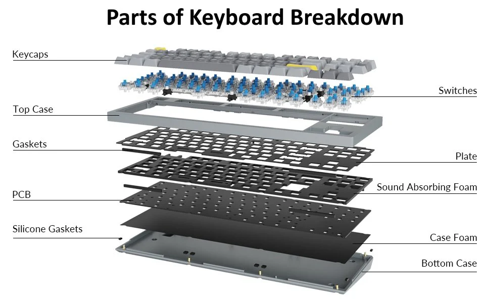
When you press a key on a computer keyboard, you are actually activating a switch. These switches are made in various ways. Below are four main types of keyboard switches explained in detail.
1. Mechanical Key Switches
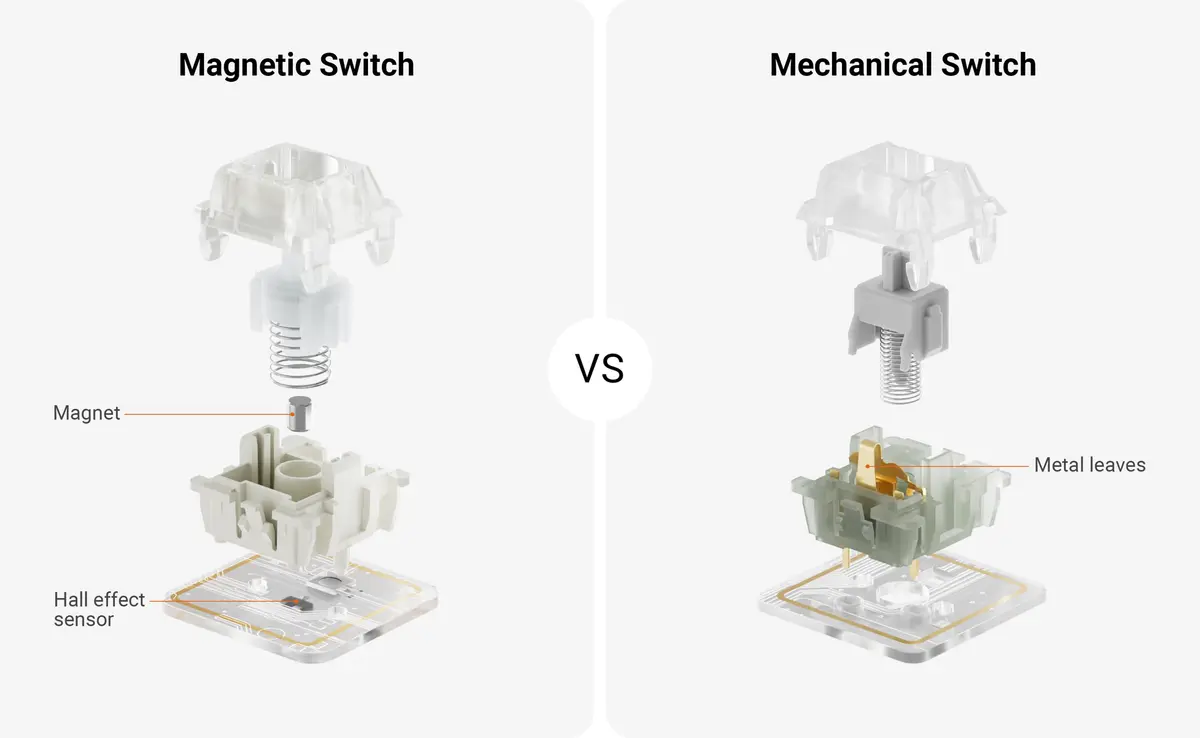
In a mechanical switch, there are two pieces of metal. When you press a key, these two metal parts touch each other and create an electrical connection. Through this connection, the keyboard tells the computer that the specific key has been pressed.
1.2. What is a Mechanical Switch Made Of?
The construction of a mechanical switch is very strong and durable:
- Metal Parts: The metal components inside the switch are typically made of phosphor-bronze, a special alloy.
- Gold Plating: The contact points are coated with gold plating. Gold is an excellent conductor and prevents rust or oxidation, ensuring the switch works well even after long-term use.
- Spring: Inside the switch, there is a small spring. When you release the key after pressing it, this spring returns the key to its original (top) position.
- Foam or Rubber: Many switches have a small piece of foam or rubber that helps reduce bouncing (rapid connecting and disconnecting) when the key is pressed.
1.3. Modern Mechanical Switches
Many mechanical switches use a silicone dome instead of metal parts:
- It looks like a small rubber dome.
- The underside of this dome has conductive rubber attached to it.
- When a key is pressed, the rubber dome collapses and the conductive rubber underneath shorts (connects) two traces on the circuit board (PCB). This signals the computer that the key has been pressed.
1.4 Problems or Disadvantages of Mechanical Switches
Although mechanical switches are relatively inexpensive, they have some notable issues:
Contact Bounce: When a key is pressed, the metal parts do not settle immediately. Instead, they rapidly connect and disconnect (bounce) several times within a few milliseconds. This can cause the computer to register a single key press as multiple presses. This problem is fixed through software using debouncing techniques.
Oxidation and Dirt: Over time, the metal parts may develop rust (oxidation) or accumulate dust. This prevents proper electrical connection and can cause keys to stop working.
1.5. Lifespan of Mechanical Switches
Durability depends on the quality of the switch:
- High-quality metal switches: Typically last about 1 million keystrokes.
- Silicone dome switches: These are much more durable and last about 25 million keystrokes. This is why silicone dome switches are more commonly used in modern high-quality keyboards.
Examples: Old IBM keyboards, Mechanical gaming keyboards (e.g., Cherry MX switches)
2. Membrane Key Switches
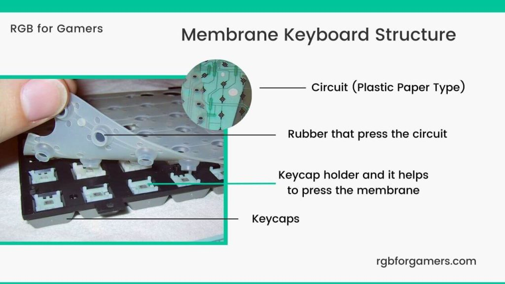
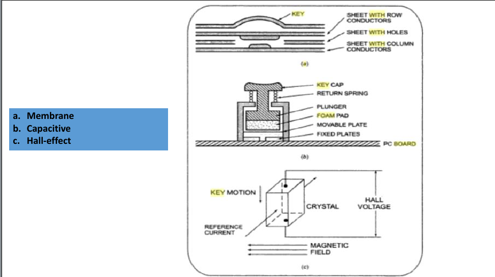
Membrane switches are actually a special type of mechanical switch. However, instead of metal parts, they use thin plastic or rubber layers (membranes).
2.1. Structure of a Membrane Switch
A membrane switch is made like a three-layer “sandwich” :
| Layer | Description |
|---|---|
| Top Layer | Thin plastic or rubber layer with silver ink conductive lines on the underside. Each key has one line beneath it. |
| Middle Layer | A perforated (hole-filled) insulating layer. Holes are present where keys are located. This layer keeps the top and bottom layers separate. |
| Bottom Layer | Has silver ink conductive lines on its upper side. Each column has one line. |
2.2. How Does a Membrane Switch Work?
Normal State: The conductive lines of the top and bottom layers remain separate due to the holes in the middle layer. No connection is made.
Key Pressed: When you press a key, the top layer is pushed downward.
Connection Made: The top layer touches the bottom layer through the holes in the middle layer.
Circuit Completes: The conductive lines of the top and bottom layers touch each other, completing an electrical circuit.
Signal Sent: The keyboard controller reads this signal and informs the computer that the key has been pressed.
Key Released: The top layer returns to its original position, breaking the connection.
2.3. Advantages of Membrane Switches
| Advantage | Description |
|---|---|
| Extremely Thin | As thin as paper, allowing for very slim devices. |
| Sealable | Can be completely sealed, protecting against dust, dirt, or liquid ingress. |
| Silent | Makes no noise when pressed. |
| Cheap | Very low production cost. |
| Lightweight | Very low weight. |
2.4. Disadvantages of Membrane Switches
| Disadvantage | Description |
|---|---|
| Low Tactile Feedback | Does not provide much physical sensation when pressed. |
| Uncertain Lifespan | Lifespan varies greatly depending on quality. |
| Difficult to Repair | If one key fails, the entire keyboard usually needs to be replaced. |
2.5. Lifespan of Membrane Switches
The lifespan of membrane keyboards varies widely :
| Type | Approximate Lifespan |
|---|---|
| Low Quality | 1-5 million keystrokes |
| Medium Quality | 5-10 million keystrokes |
| High Quality | 10-20 million keystrokes |
2.7. Membrane vs. Mechanical Switch (Comparison)
| Feature | Membrane Switch | Mechanical Switch |
|---|---|---|
| Structure | Three thin layers | Metal parts + Spring |
| Cost | Very cheap | Comparatively expensive |
| Noise | Silent | Noisy (click sound) |
| Tactile Feedback | Low | High |
| Thickness | Extremely thin | Thick |
| Sealable | Yes | Difficult |
| Lifespan | 1-20 million | 1-25 million |
| Repair | Difficult (replace entire keyboard) | Individual switches can be replaced |
Examples: Laptop keyboards, Phone keypads, Remote controls
3. Capacitive Key Switches
are a modern and advanced keyboard switch technology. Instead of using mechanical contact, they work by detecting changes in capacitance.
3.1. Structure of a Capacitive Switch
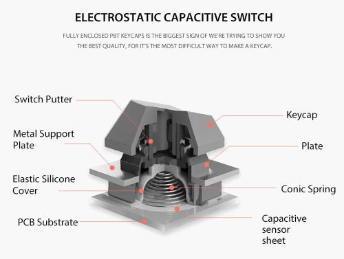
Capacitive switches do not use metal contact. Instead, they are made up of:
| Component | Description |
|---|---|
| Fixed Metal Plates | Two small metal plates are placed on the Printed Circuit Board (PCB). These remain stationary. |
| Movable Metal Plate | Another metal plate is attached to the underside of a foam or rubber piece. This plate moves downward when the key is pressed. |
3.2. How Does a Capacitive Switch Work?
Step-by-Step Working Process:
Step 1: Normal State (Key Not Pressed)
- There is a specific distance between the fixed and movable plates.
- This distance creates a specific capacitance value.
Step 2: Key Pressed
- When you press the key, the movable plate moves downward.
- This reduces the distance between the movable and fixed plates.
Step 3: Capacitance Changes
- As distance decreases, the capacitance value changes.
- Formula: C = εA/d (When distance decreases, capacitance increases)
Step 4: Sense Amplifier Generates Signal
- A special sense amplifier circuit detects this change.
- It produces a logic level signal (0 or 1).
- This signal tells the microprocessor that the key has been pressed.
Step 5: Key Released
- Due to the elasticity of the foam or rubber, the movable plate returns to its original position.
- The distance returns to normal, and capacitance returns to its original value.
3.3. Simple Diagrammatic Concept
Normal State:                    Key Pressed:
[Movable Plate]                  [Movable Plate]
     |                                ↓ (moved down)
     | Distance = d                   | Distance = d' (less)
[Fixed Plate]                    [Fixed Plate]
[Fixed Plate]                    [Fixed Plate]

Capacitance = C                  Capacitance = C' (higher)
3.4. Advantages of Capacitive Switches
| Advantage | Description |
|---|---|
| No Mechanical Contact | No metal contact means no oxidation or dirt issues. |
| Long-lasting | No mechanical wear, so lifespan is very high. |
| Reliable | No bouncing problems. |
| Fast Response | Works extremely quickly. |
| Silent | Makes no noise when pressed. |
3.5. Disadvantages of Capacitive Switches
| Disadvantage | Description |
|---|---|
| Extra Circuitry Required | Needs special sense amplifier circuits to detect capacitance changes. |
| Higher Cost | Design and production costs are higher than standard switches. |
| Complex Design | Circuit design is relatively complex. |
Examples: Apple Magic Keyboard, Many high-end laptop keyboards
4. Hall Effect Key Switches
When an electric current flows through a conductor or semiconductor and a perpendicular magnetic field is applied to it, a small voltage is generated perpendicular to the direction of current. This voltage is called the Hall Voltage.
In simple words: When you bring a magnet near an electric current, a small voltage is created.
4.2. Structure of a Hall Effect Switch
| Component | Description |
|---|---|
| Semiconductor Crystal | A special semiconductor crystal (such as silicon or gallium arsenide) |
| Reference Current | A fixed electric current is passed through two opposite surfaces of this crystal |
| Magnet | A small magnet that moves closer to the crystal when the key is pressed |
| Sensing Circuit | Circuit that detects and amplifies the generated Hall voltage |
4.3. How Does a Hall Effect Switch Work?
Step-by-Step Working Process:
Step 1: Normal State (Key Not Pressed)
- A reference current flows through the semiconductor crystal.
- The magnet is far away from the crystal.
- No Hall voltage is generated.
Step 2: Key Pressed
- When you press the key, the magnet moves closer to the crystal.
- The magnet creates a magnetic field on the crystal.
Step 3: Hall Voltage is Generated
- The magnetic flux lines are perpendicular to the direction of current.
- This creates a small voltage (Hall voltage) across the other two opposite surfaces of the crystal.
Step 4: Signal is Created
- This tiny voltage is amplified by an amplifier circuit.
- The amplified signal tells the microprocessor that the key has been pressed.
Step 5: Key Released
- The magnet returns to its original position.
- The magnetic field decreases and the Hall voltage disappears.
4.4. Simple Diagrammatic Concept
Normal State:                    Key Pressed:
[Magnet] ★ Far away              [Magnet] ★ Close (moved near)
     |                                  |
[Semiconductor]                  [Semiconductor]
     | (Current)                      | (Current)
     ↓                                ↓
No Voltage Generated          Hall Voltage is Generated
4.5. Advantages of Hall Effect Switches
| Advantage | Description |
|---|---|
| No Mechanical Contact | No metal contact means no wear, oxidation, or dirt issues. |
| Extremely Long-lasting | No mechanical wear, so lifespan is very high. |
| Highly Reliable | No bouncing problems. |
| Fast Response | Works extremely quickly. |
| Silent | Makes no noise when pressed. |
4.6. Disadvantages of Hall Effect Switches
| Disadvantage | Description |
|---|---|
| Higher Cost | More expensive than other switches due to complex mechanism. |
| Complex Structure | Maintaining proper positioning of magnet and sensor is difficult. |
4.8. Hall Effect vs. Other Switches (Comparison)
| Feature | Mechanical | Membrane | Capacitive | Hall Effect |
|---|---|---|---|---|
| Working Principle | Metal contact | Layer contact | Capacitance | Magnet + Hall Voltage |
| Oxidation | Yes | Low | None | None |
| Bounce | Yes | Low | None | None |
| Lifespan (million) | 1-25 | 1-20 | ~20 | 100+ |
| Cost | Cheap | Very cheap | Moderate | Expensive |
| Noise | Noisy | Silent | Silent | Silent |
4.9. Other Uses of Hall Effect Sensors
Hall Effect sensors are not only used in keyboards but also in many other applications:
- Electrically Controlled Machines – to detect speed
- Motor Control – to determine rotation speed and position
- Automobiles – to measure wheel and engine speed
- Robotics – to control position and movement
4.10. Where Are Hall Effect Switches Used?
- High-end Keyboards – where reliability and durability are important
- Industrial Control Panels – in harsh environments
- Aircraft and Spacecraft Control Panels – for extreme reliability
- Medical Devices – where cleanliness is required
Examples: Specialized gaming keyboards, Industrial-use keyboards
Comparison of the Four Methods:
| Feature | Mechanical | Membrane | Capacitive | Hall Effect |
|---|---|---|---|---|
| Working Principle | Metal contact | Layer contact | Capacitance change | Magnet + Sensor |
| Cost | Cheap | Very cheap | Moderate | Expensive |
| Sound | Noisy | Silent | Silent | Silent |
| Durability | Good | Moderate | Good | Excellent |
| Speed | Good | Slow | Fast | Extremely fast |
| Usage | Gaming keyboards | Laptops, Remotes | High-end keyboards | Specialized keyboards |
Keyboard Circuit Connections and Interfacing –
Why the Matrix Method?
| Method | Number of Wires | Example |
|---|---|---|
| Direct Connection | 100 keys = 100 wires | Complex, expensive, takes more space |
| Matrix Connection | 100 keys = 10 rows + 10 columns = 20 wires | Simple, cheap, takes less space |
1. Three Main Tasks to Get Data from a Keyboard
To get meaningful data from a keyboard, the following three tasks must be completed:
| Task | Description | Why Needed |
|---|---|---|
| 1. Detect a Keypress | Identify whether any key has been pressed | The keyboard needs to know when the user is pressing a key |
| 2. Debounce the Keypress | Eliminate the bounce generated when a key is pressed | To prevent a single press from being counted as multiple presses |
| 3. Encode the Keypress | Determine the identity (scan code) of the pressed key | To tell the computer which key has been pressed |
2. These three tasks can be done using
- hardware
- software
- combination of both.
Method 1: Pure Hardware Method
All three tasks are done using dedicated electronic circuits – no software needed.
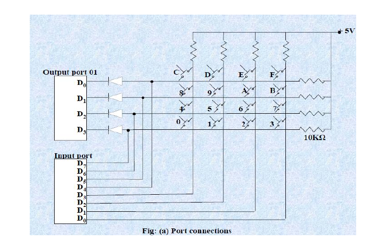
How 4*8 matrix Works:
Step 1: Detect a Keypress
| Action | Details |
|---|---|
| Set ALL Rows LOW | Port A = 0000 |
| Read Columns | Check Port B |
Result:
- No key pressed → Port B =
1111(all HIGH) - Key pressed (e.g., Row 1, Column 2) → Port B =
1011(one column becomes LOW)
Key Detected!
Step 2: Debounce (Wait 20ms)
| Action | Details |
|---|---|
| First signal | Column becomes LOW |
| Wait 20ms | Let mechanical bounce settle |
| Read Columns Again | Check Port B once more |
Result:
- If HIGH now → Bounce → Ignore
- If still LOW → Valid keypress
Step 3: Encode (Find the Key)
Scan one row at a time:
| Row | Port A Value | Action |
|---|---|---|
| Row 0 | 1110 | Read columns → No key |
| Row 1 | 1101 | Read columns → Column 2 LOW → Key Found! |
| Row 2 | 1011 | Read columns → Check next |
| Row 3 | 0111 | Read columns → Check next |
Key Found at:
- Row = 1 (Port A =
1101) - Column = 2 (Port B =
1011)
Look-up Table → Scan Code → e.g., 0x06 for key ‘5’
| Advantage | Disadvantage |
|---|---|
| Very fast (nanoseconds) | Expensive (many components) |
| No CPU load | Complex circuit design |
| Highly reliable | Cannot be changed easily |
Method 2: Pure Software Method
All three tasks are done by microprocessor program – no extra hardware needed.
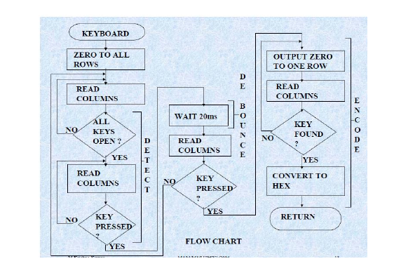
This woking Princile of the software based keyboard intrfacing
Block 1: DETECT (Find a Keypress)
| Step | Action |
|---|---|
| 1 | Set ALL ROWS to LOW (0V) |
| 2 | READ COLUMNS – check if any is LOW |
| 3 | If ALL columns HIGH → No key pressed → Keep waiting |
| 4 | If ANY column LOW → Key pressed! → Move to DEBOUNCE |
Block 2: DEBOUNCE (Remove Bounce)
| Step | Action |
|---|---|
| 1 | WAIT 20ms (let mechanical bounce settle) |
| 2 | READ COLUMNS AGAIN |
| 3 | If column is HIGH now → It was just noise → Go back to DETECT |
| 4 | If column is still LOW → Valid keypress → Move to ENCODE |
Block 3: ENCODE (Identify & Send Code)
| Step | Action |
|---|---|
| 1 | Set ONE ROW to LOW at a time (scan row by row) |
| 2 | READ COLUMNS for that row |
| 3 | If column is LOW → KEY FOUND at (Row, Column) |
| 4 | CONVERT TO HEX (scan code like 0x1E) |
| 5 | SEND CODE to computer → Go back to DETECT |
| Advantage | Disadvantage |
|---|---|
| No extra hardware needed | Slower (CPU spends time scanning) |
| Easy to customize | CPU load is high |
| Very cheap | Timing must be precise |
Method 3: Hybrid Method (Hardware + Software)
Some work in hardware, some in software. Most modern keyboards use this.
| Task | How It’s Done | Who Does It |
|---|---|---|
| Detect | Microcontroller scans rows/columns | Hardware (MCU) |
| Debounce | RC circuit + firmware delay | Both (Hardware + Software) |
| Encode | Firmware converts scan code to USB HID | Software (Firmware) |
Advantage and Disadvantage
| Advantage | Disadvantage |
|---|---|
| Best of both worlds | More complex design |
| Fast and reliable | Requires programming (firmware) |
| Flexible and cheap | Development takes time |
Which Keyboard Uses Which Method?
| Keyboard Brand / Model | Method Used | Why |
|---|---|---|
| IBM Model M (1980s) | Pure Hardware | No microcontroller inside |
| Apple Magic Keyboard | Hybrid | Microcontroller + firmware |
| Logitech G Series | Hybrid | Fast gaming response |
| Arduino 4x4 Keypad | Pure Software | No extra ICs needed |
| Cherry Mechanical Keyboard | Hybrid | USB + firmware for RGB |
| Old PS/2 Keyboard | Hardware / Hybrid | Depends on model |
8086-এর সাথে 8255 ব্যবহার করে 4×4 Keyboard ইন্টারফেসিং এবং ALP
1. System Architecture & Hardware Connection
4×4 ম্যাট্রিক্স কী-এর কাজ করার পদ্ধতি:
4×4 keyboard-এ 16টি কী আছে, যা 4টি সারি (Row) এবং 4টি কলাম (Column)-এ সাজানো। একটি কী চাপলে সংশ্লিষ্ট সারি এবং কলামের মধ্যে সংযোগ তৈরি হয়। এই সংযোগ সনাক্ত করাই হলো keyboard scanning-এর মূল কাজ।
8255 PPI-এর সাথে সংযোগ:
- Port B (PB0–PB3) → 4টি সারি (Row lines) - এখানে আউটপুট হিসেবে কনফিগার করে ধারাবাহিকভাবে 0 দেওয়া হবে (row scanning)
- Port C (PC0–PC3) → 4টি কলাম (Column lines) - এখানে ইনপুট হিসেবে কনফিগার করে কলামের অবস্থা পড়া হবে
- Port A → ব্যবহার না করলে ইনপুট/আউটপুট যেকোনোভাবে রাখা যায়
পোর্ট অ্যাড্রেস নির্ধারণ:
8255-এর Control Register: 86H  (ধরে নিচ্ছি)
Port A: 80H
Port B: 82H
Port C: 84H
সতর্কতা: পোর্ট অ্যাড্রেস আপনার সার্কিটের Chip Select (CS) লজিকের উপর নির্ভর করে পরিবর্তিত হবে。
2. 8255-এর Control Word কনফিগারেশন
Mode 0 (Basic I/O): 8255-কে Mode 0-এ কনফিগার করলে পোর্টগুলো সরল ইনপুট/আউটপুট হিসেবে কাজ করে।
Control Word (CW):
| বিট (D7–D0) | মান | অর্থ |
|---|---|---|
| D7 | 1 | I/O Mode (Active) |
| D6, D5 | 00 | Mode 0 (Group A) |
| D4 | 0 | Port A = Output |
| D3 | X | Port C Upper (PC7–PC4) =不重要 (ব্যবহার হবে না) |
| D2 | 0 | Mode 0 (Group B) |
| D1 | 0 | Port B = Output (সারি scan করার জন্য) |
| D0 | 1 | Port C Lower (PC3–PC0) = Input (কলাম পড়ার জন্য) |
Control Word = 10000001₂ = 81H
মনোযোগ: Port B আউটপুট এবং Port C (PC0–PC3) ইনপুট হিসেবে কনফিগার করতে D1=0 এবং D0=1 করতে হবে।
3. Keyboard Scanning Algorithm (Flowchart)
নিচের ধাপগুলো অনুসরণ করে কী প্রেস সনাক্ত করা হয়:
- সব সারি Low করুন: Port B-তে
00Hআউটপুট দিন (সব সারি 0)। - কলাম পড়ুন: Port C থেকে ইনপুট নিন।
- কী প্রেস চেক করুন: যদি Port C-এর নিচের ৪ বিট (PC3–PC0) সব 1 হয় (
0FH), তাহলে কোনো কী চাপা নেই → ধাপ 1-এ ফিরে যান। - Debounce (প্রথমবার): 10ms Delay কল করুন (DEBOUNCE routine ব্যবহার করে)।
- পুনরায় কলাম পড়ুন: আবার Port C পড়ে নিশ্চিত করুন যে এটি সত্যিই কোনো কী প্রেস, এবং নয়তো ভুল signal (ধাপ 1-এ ফিরে যান)।
- কোন কলাম চিহ্নিত করুন: কোন বিট 0 হয়েছে তা দেখে কলাম নম্বর বের করুন।
- সারি Scan করুন: এখন একটি একটি করে সারি 0 করে বাকি সারি 1 রেখে Port B-তে আউটপুট দিন:
0EH(PB0=0, বাকি 1) → সারি 00DH(PB1=0, বাকি 1) → সারি 10BH(PB2=0, বাকি 1) → সারি 207H(PB3=0, বাকি 1) → সারি 3
- সারি চিহ্নিত করুন: প্রতিবার Port C পড়ুন। যেই সারিতে 0 পাবেন, সেটি চিহ্নিত করুন এবং সারি নম্বর বের করুন।
- কী-কোড তৈরি করুন: সারি ও কলাম নম্বর ব্যবহার করে Lookup Table থেকে আসল কী-কোড (যেমন 0–F) বের করুন।
- Debounce (দ্বিতীয়বার): কী রিলিজের সময়ও bounce হয়, তাই আবার 10ms Delay দিন এবং নিশ্চিত করুন যে কী রিলিজ হয়েছে।
4. Complete ALP (Assembly Language Program)
;-----------------------------------------------------------
; 4x4 Keyboard Interfacing with 8255 (8086)
; Detects key press, debounces (10ms), returns key code in AL
;-----------------------------------------------------------

DATA SEGMENT
    ; Lookup Table: Key codes for 4x4 keyboard (0-F)
    KEY_TABLE DB 00H, 01H, 02H, 03H
              DB 04H, 05H, 06H, 07H
              DB 08H, 09H, 0AH, 0BH
              DB 0CH, 0DH, 0EH, 0FH
DATA ENDS

CODE SEGMENT
    ASSUME CS:CODE, DS:DATA

START:
    MOV AX, DATA
    MOV DS, AX

    ;-------------------------------------------------------
    ; Step 1: Initialize 8255 in Mode 0
    ; Control Word = 81H (Port B=Output, Port C Lower=Input)
    ;-------------------------------------------------------
    MOV AL, 81H
    OUT 86H, AL          ; Write to Control Register

SCAN_LOOP:
    ;-------------------------------------------------------
    ; Step 2: Check if any key is pressed
    ;-------------------------------------------------------
    MOV AL, 00H          ; All rows = 0 (active low)
    OUT 82H, AL          ; Write to Port B (rows)

    IN AL, 84H           ; Read from Port C (columns)
    AND AL, 0FH          ; Mask only lower 4 bits (PC0-PC3)

    CMP AL, 0FH          ; All columns high? (no key pressed)
    JE SCAN_LOOP         ; Yes, continue polling

    ;-------------------------------------------------------
    ; Step 3: Debounce (First time) - Wait 10ms
    ;-------------------------------------------------------
    CALL DEBOUNCE        ; 10ms delay routine

    ;-------------------------------------------------------
    ; Step 4: Read columns again to confirm key press
    ;-------------------------------------------------------
    IN AL, 84H
    AND AL, 0FH
    CMP AL, 0FH
    JE SCAN_LOOP         ; False trigger, go back

    ;-------------------------------------------------------
    ; Step 5: Identify which column is pressed
    ;-------------------------------------------------------
    MOV CL, 00H          ; CL = Column counter (starting from 0)
    MOV BL, AL           ; Save column status in BL

FIND_COLUMN:
    ROR BL, 1            ; Rotate right to check each bit
    JC COLUMN_FOUND      ; If carry=1, bit was 1 (not pressed)
    INC CL               ; Increment column counter
    CMP CL, 04H          ; Checked all 4 columns?
    JL FIND_COLUMN       ; No, continue

COLUMN_FOUND:
    ; CL now contains column number (0-3)

    ;-------------------------------------------------------
    ; Step 6: Scan rows one by one
    ;-------------------------------------------------------
    MOV DL, 00H          ; DL = Row counter (starting from 0)
    MOV BH, 0EH          ; BH = Row scan pattern (PB0=0 first)

FIND_ROW:
    MOV AL, BH
    OUT 82H, AL          ; Activate current row

    IN AL, 84H           ; Read columns
    AND AL, 0FH
    CMP AL, 0FH
    JNE ROW_FOUND        ; If not all high, row found

    ROL BH, 1            ; Rotate left to activate next row
    INC DL
    CMP DL, 04H
    JL FIND_ROW          ; Check next row

ROW_FOUND:
    ; DL now contains row number (0-3)

    ;-------------------------------------------------------
    ; Step 7: Calculate key code using lookup table
    ; Key Code = Row * 4 + Column
    ;-------------------------------------------------------
    MOV AL, DL           ; AL = Row number
    MOV CL, 02H
    SHL AL, CL           ; Multiply row by 4 (SHL by 2)
    ADD AL, CL           ; Add column number

    ; Now AL = Key index (0-15)
    LEA BX, KEY_TABLE    ; BX points to lookup table
    XLAT                 ; AL = KEY_TABLE[AL] (key code)

    ; AL now contains the actual key code (0-F)

    ;-------------------------------------------------------
    ; Step 8: Debounce on release - Wait for key to be released
    ;-------------------------------------------------------
WAIT_RELEASE:
    MOV AL, 00H
    OUT 82H, AL          ; All rows low

    IN AL, 84H
    AND AL, 0FH
    CMP AL, 0FH
    JNE WAIT_RELEASE     ; Wait until all columns high

    CALL DEBOUNCE        ; 10ms delay for release bounce

    ;-------------------------------------------------------
    ; Step 9: Exit with key code in AL
    ;-------------------------------------------------------
    MOV AH, 4CH          ; DOS exit function (optional)
    INT 21H

;-----------------------------------------------------------
; Subroutine: DEBOUNCE (10ms delay)
; Assumes DEBOUNCE is an available 10ms delay routine
;-----------------------------------------------------------
DEBOUNCE PROC NEAR
    ; If delay routine is already available, call it directly
    ; Otherwise, implement a delay loop (example for 5MHz clock)
    PUSH CX
    MOV CX, 5000H       ; 10ms delay loop count (adjust as needed)
DELAY_LOOP:
    LOOP DELAY_LOOP
    POP CX
    RET
DEBOUNCE ENDP

CODE ENDS
END START
5. ALP-এর ব্যাখ্যা
| বিভাগ | কাজ |
|---|---|
| Initialize 8255 | 81H Control Word দিয়ে 8255 কে Mode 0-এ সেট করা হয়েছে। Port B আউটপুট (সারি scan) এবং Port C ইনপুট (কলাম পড়া)। |
| Wait for Key Press | সব সারি Low করে (00H) Port C পড়া হচ্ছে। যদি কোনো কলাম 0 হয়, বুঝতে হবে কী চাপা হয়েছে। |
| Debounce | 10ms delay (DEBOUNCE routine) কল করে mechanical bounce-এর প্রভাব কমানো হয়েছে। |
| Identify Column | Port C-এর 4 বিট পরীক্ষা করে কোন কলামে 0 পাওয়া গেছে তা চিহ্নিত করা হয়েছে। |
| Scan Rows | ধারাবাহিকভাবে প্রতিটি সারি 0 করে বাকি সারি 1 রেখে Port B-তে আউটপুট দিয়ে পড়া হচ্ছে। কোন সারিতে 0 পাওয়া গেছে তা চিহ্নিত করা হয়েছে। |
| Calculate Key Code | সনাক্তকৃত সারি ও কলাম নম্বর থেকে Lookup Table-এর মাধ্যমে 0–F পর্যন্ত কী-কোড বের করা হয়েছে। |
| Wait for Release | কী রিলিজ না হওয়া পর্যন্ত অপেক্ষা করে আবার Debounce করা হয়েছে, যাতে একটি প্রেসে একাধিক সনাক্তকরণ না হয়। |
| Return Key Code | AL রেজিস্টারে কী-কোড রেখে প্রোগ্রাম শেষ হয়েছে (অথবা main program-এ ফিরে গেছে)। |
প্রশ্ন: 8086-এর সাথে 8255 ব্যবহার করে 4×4 Keyboard ইন্টারফেসিং এবং Key Detection-এর জন্য ALP লিখুন।
উত্তর:
4×4 keyboard-এ কী প্রেস সনাক্ত করতে 8255-কে Mode 0-এ কনফিগার করে Port B-কে Output (সারি scan) এবং Port C-কে Input (কলাম পড়া) হিসেবে সেট করতে হবে। Control Word হবে 81H। প্রথমে সব সারি Low করে Port C পড়ে কোনো কী প্রেস আছে কিনা দেখতে হবে। Debounce-এর জন্য 10ms Delay (DEBOUNCE routine) কল করতে হবে। তারপর ধারাবাহিকভাবে প্রতিটি সারি Scan করে কোন সারিতে কী প্রেস হয়েছে তা চিহ্নিত করতে হবে। সনাক্তকৃত সারি ও কলাম নম্বর ব্যবহার করে Lookup Table থেকে কী-কোড বের করে AL রেজিস্টারে রিটার্ন করতে হবে। সবশেষে কী রিলিজ হওয়া পর্যন্ত অপেক্ষা করে আবার Debounce করতে হবে।