Peripherals And Interfacing
A display (commonly called a screen or monitor)
is an electronic output device that visually presents text, graphics, and video generated by a computer, microcontroller, or other graphic-producing devices.It acts as the primary visual interface between humans and machines.
Core Concepts of a Display
1. A pixel (picture element)
is the smallest controllable unit of a digital display. Millions of pixels form an image.
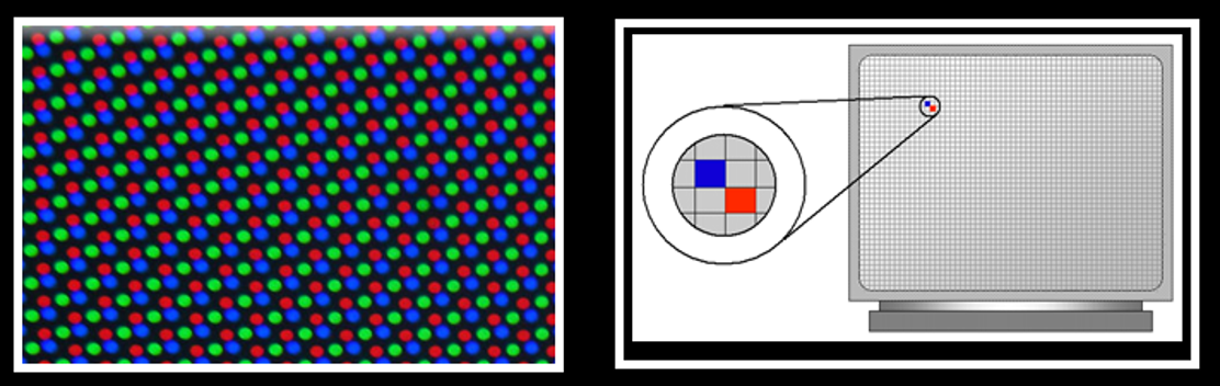
Subpixel Structure: A single pixel is not a single white dot; it consists of three rectangular subpixels: Red (R), Green (G), and Blue (B).
Color Mixing: By varying the light intensity of these three colors, the screen creates millions of colors. For example, Red + Green (with Blue off) = Yellow.
LCD,LED and OLED Pixel Structure
- Modern Layout (Matrix Grid): In modern flat-panel displays, these RGB subpixels are arranged side-by-side as thin vertical strips. Together, one set of Red, Green, and Blue strips forms a single square pixel.
CRT Pixel Structure
- Phosphor Triad: The circular dots on the left represent Red, Green, and Blue (RGB) phosphor dots coated inside a CRT screen. They are arranged in a triangular cluster called a triad.
- Electron Guns: Three separate electron guns (one for each color) fire beams from behind the monitor to strike these specific dots.
- Mechanism: When struck by the electron beams, these RGB dots light up at different intensities, blending together to form a single colored pixel to the human eye.
2. Resolution
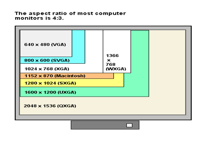
The total number of distinct pixels a display can show, written as width × height.
- Example: Full HD (1080p) is $1920 \times 1080$ pixels, meaning it contains over 2 million pixels on the screen.
1. Modern Widescreen Standards
- The Shift: Displays evolved from boxy 4:3 shapes to wider formats to match modern media.
- 16:9 Ratio (Universal Standard): The standard for video, streaming, and gaming.
- FHD (Full High Definition): $1920 \times 1080$ pixels
- QHD (Quad High Definition / 2K): $2560 \times 1440$ pixels
- UHD (Ultra High Definition / 4K): $3840 \times 2160$ pixels
2. Classic(old) Standard Resolutions
| Abbreviation | Full Meaning | Resolution | Key Fact |
|---|---|---|---|
| VGA | Video Graphics Array | $640 \times 480$ | Early computer baseline standard. |
| SVGA | Super Video Graphics Array | $800 \times 600$ | Early upgrade for more workspace. |
| XGA | Extended Graphics Array | $1024 \times 768$ | Popular standard in the late 90s/2000s. |
| WXGA | Wide Extended Graphics Array | $1366 \times 768$ | Widescreen version used on older laptops. |
| SXGA | Super Extended Graphics Array | $1280 \times 1024$ | Boxy, professional monitor standard. |
| UXGA | Ultra Extended Graphics Array | $1600 \times 1200$ | High-end standard for large CRT/early LCDs. |
| QXGA | Quantum Extended Graphics Array | $2048 \times 1536$ | Ultra-high resolution standard for its era. |
3. Refresh
- Persistence: The temporary glow of screen phosphors/pixels that quickly fades away after being lit.
- Refreshing: The constant process of redrawing the image on screen to prevent it from fading or flickering.
- Refresh Rate: Measured in Hertz (Hz), it is the number of times a screen updates its image per second (e.g., $60\text{ Hz}$ means 60 times/second). Higher resolutions require stronger hardware to run at fast refresh rates.
How to Check Laptop’s Refresh Rate
- Windows: Settings $\rightarrow$ System $\rightarrow$ Display $\rightarrow$ Advanced display $\rightarrow$ Choose a refresh rate.
- Web Browser (Quickest): Go to testufo.com to see your live refresh rate instantly.
RGB vs. CMYK (Screen vs. Printing)
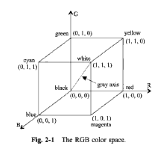
- RGB (Red, Green, Blue): This is a light-based (additive) color model. It creates colors by adding light wavelengths together onto an inherently black screen. When all three primary lights are combined at maximum intensity, they produce white light.
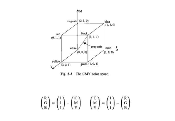
- CMYK (Cyan, Magenta, Yellow, Key/Black): This is an ink-based (subtractive) color model. It works by layering ink onto inherently white paper to subtract (absorb) specific light wavelengths from reflecting into your eyes.
Why can’t we use RGB ink on paper?
- Inks mix by absorbing light, not emitting it. If you mix physical Red and Green inks on paper, they absorb almost all light and create a muddy, dark brown color—not yellow like they do on a digital screen. To accurately control light reflection from white paper, printers must use Cyan, Magenta, and Yellow (CMY) inks.
Color Cubes & Model Conversion
Color spaces are mathematically modeled as 3D geometric cubes, where every specific color coordinate is normalized between $0$ and $1$.
RGB Cube: Starts at the origin point of absolute darkness/black $(0, 0, 0)$ and ends at pure white $(1, 1, 1)$.
CMY Cube: The exact geometric inverse of the RGB cube. It starts at clean white paper $(0, 0, 0)$ and ends at absolute absorption/black $(1, 1, 1)$.
Conversion Formula: Because they are exact structural opposites (complementary colors), converting between them is a simple subtraction from $1$:
$\text{CMY} = 1 - \text{RGB}$ (Used to Send Data to the Printer)This is used when you click “Print”. The computer takes your digital screen light values (RGB) and subtracts them from $1$ to calculate exactly how much Cyan, Magenta, and Yellow ink the printer head needs to spray onto the white page.
$\text{RGB} = 1 - \text{CMY}$ (Used by Printer Software to Predict Colors)This is used when the printer software wants to double-check or preview how a certain mix of inks on paper will actually look to the human eye. By subtracting the ink values (CMY) from a pure white light source ($1$), it calculates the final reflected RGB light wavelengths that will hit your eyes.
How the Inks Act as Filters (The Subtraction)
- When you look at a clean piece of white paper under a normal lightbulb or daylight, you are looking at White Light. White light isn’t a single color; it is a combination of all visible wavelengths—primarily Red, Green, and Blue (RGB) light mixed together.CMY inks are semi-transparent chemical dyes. They don’t generate color; instead, they act like molecular “filters” that capture and trap exactly one primary color of light, Cyan Ink subtracts Red: When white light (RGB) hits Cyan ink, the chemical structure of the ink absorbs (kills) the Red light waves. Only Green and Blue light escape and bounce back to your eyes. Your brain sees Green + Blue and interprets it as Cyan.$$\text{White (R+G+B)} - \text{Red} = \text{Cyan (G+B)}$$
Digital Color Coding (Computer Memory)
Computers look at memory management in two distinct ways when storing pixel color values:
- Direct 3-Bit Coding: The system allocates exactly $1\text{ bit}$ per primary color ($1\text{ bit for } R$, $1\text{ bit for } G$, $1\text{ bit for } B$). Since each bit can only be completely Off ($0$) or On ($1$), this setup can only produce $2^3 = 8$ total possible colors (e.g.,
1 1 0= Yellow). - Indexed Color / Look-Up Table (LUT) Method: A highly efficient approach designed to display millions of colors without exhausting system video memory.
The Types of Video Display Devices Available
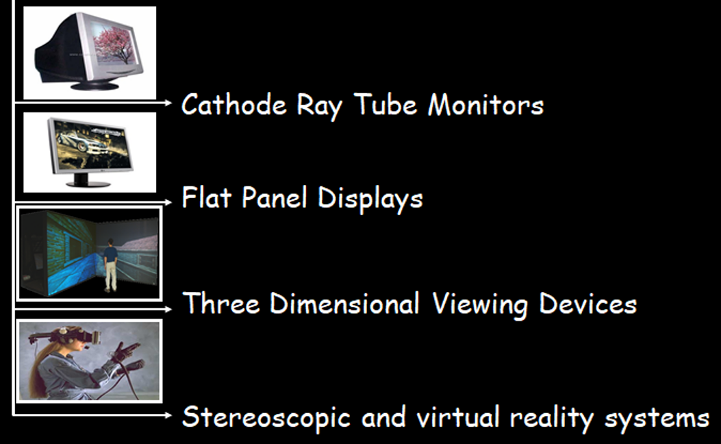 Monitors Explained - LCD, LED, OLED, CRT, TN, IPS, VA
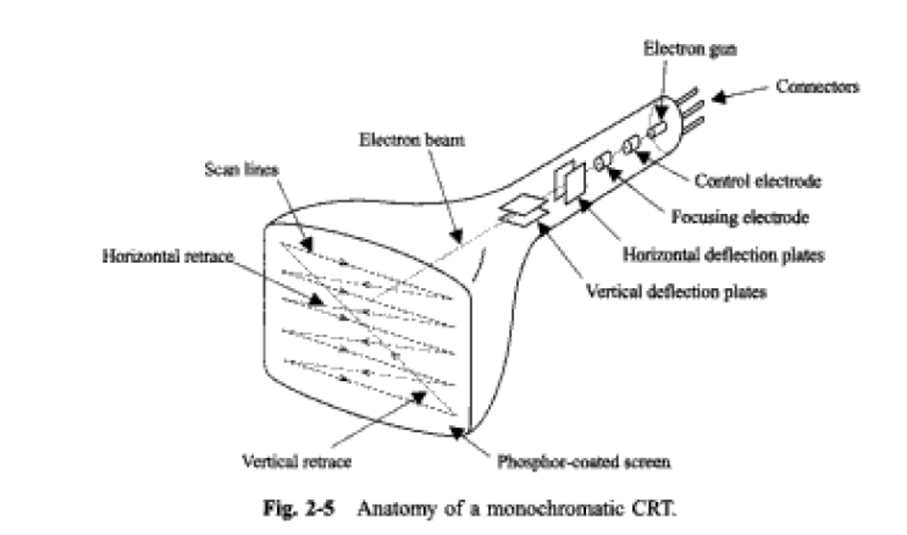
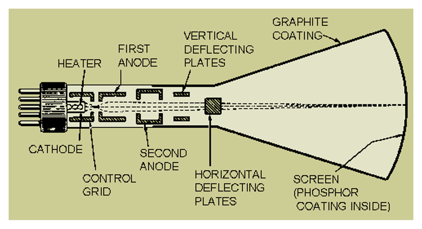
1. A CRT display
is a vacuum glass tube that houses three main functional areas to generate, steer, and display an image.
A. Beam Generation & Control (The Electron Gun)
Located at the narrow neck of the tube, this assembly creates and shapes the electron beam:
- Connectors: Pins at the very back that feed power and signals into the monitor.
- Cathode: A heated element that emits a continuous stream of electrons via heat (thermionic emission).
- Control Grid (Control Electrode): Regulates the brightness. By changing the voltage here, it controls how many electrons pass through, determining how bright a spot will be.
- Focusing Anode (Focusing Electrode): Uses electrostatic fields to sharpen the scattered electrons into a thin, crisp beam.
B. Beam Deflection (The Steering System)
Once the beam is focused, it must be steered across the screen using an electrostatic setup:
- Horizontal Deflection Plates: Parallel vertical plates that use changing voltages to steer the beam left and right across the screen.
- Vertical Deflection Plates: Parallel horizontal plates that steer the beam up and down to move it from line to line.
C. The Display Target
- Electron Beam: The highly accelerated, focused stream of electrons traveling down the vacuum tube.
- Phosphor-Coated Screen: The inside surface of the front glass screen. It is coated with phosphorescent material that glows and emits visible light whenever the high-energy electron beam hits it.
The Core Working Principle
The entire system functions using two main scientific steps:
- Electron Emission: Heat forces electrons out of the cathode at the back of the tube.
- Phosphorescence: The accelerated electron beam flies through the vacuum tube, hits the phosphor-coated screen at the front, and transforms that kinetic energy into the visible light you see.
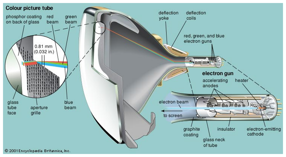
1.2 Color CRT Technologies
Color CRT monitors display images using two distinct methodologies: the Beam-Penetration Method and the Shadow Mask Method. They differ fundamentally in their engineering, color capabilities, and practical use cases.
https://vivadifferences.com/difference-between-beam-penetration-and-shadow-mask-method/
1. Beam-Penetration Method
- How it works: It utilizes a single electron gun paired with two concentric layers of phosphor (outer Red and inner Green) on the screen. The display color is determined by varying the acceleration voltage of the electron beam, controlling how deeply it penetrates the phosphor layers.
- Capabilities: It has a limited color spectrum (only producing Red, Orange, Yellow, and Green) and offers lower overall picture quality. However, it provides a cost-effective solution for specialized vector displays.
- Real-World Applications: Historically used in systems requiring precise line rendering (Random-Scan/Vector monitors) rather than complex imagery. Key examples include military radar systems (highlighting threats in red against a green backdrop), early Air Traffic Control (ATC) displays, and first-generation CAD workstations for architectural wireframes.
2. Shadow Mask Method
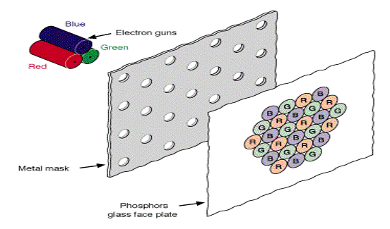
- How it works: This system features three separate electron guns (one each for Red, Green, and Blue) focused on a screen composed of pixel triads (triangles of R, G, and B phosphor dots). A perforated metal sheet (the shadow mask) ensures each gun’s beam strikes only its corresponding color dot.
- Capabilities: By blending different intensities of primary RGB lights, it produces a much wider color spectrum and delivers high-quality, realistic images suitable for complex graphics.
- Real-World Applications: This is the foundational technology behind the mainstream consumer electronics we grew up with. Key examples include classic color televisions (e.g., Sony Trinitron, Panasonic), legacy desktop computer monitors from the Windows 95/XP eras, and retro arcade gaming cabinets (Street Fighter, Pac-Man).
1.3 Draw images in the CRT display
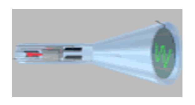
1. Random Scan (Vector Scan)
https://www.youtube.com/watch?v=9xGXrS6q660&t=330s
- How it draws: The electron beam draws lines only where needed. It goes directly to specific points and draws vectors (straight lines).
- Refresh needed? Yes – it must redraw the image constantly to prevent fading.
- Resolution: Very high – produces smooth lines and curves.
- Flicker: Low, because it only draws the necessary lines.
- Animation ability: Weak – too slow for complex moving images.
- Used in: Old CAD systems, lab equipment, oscilloscopes.
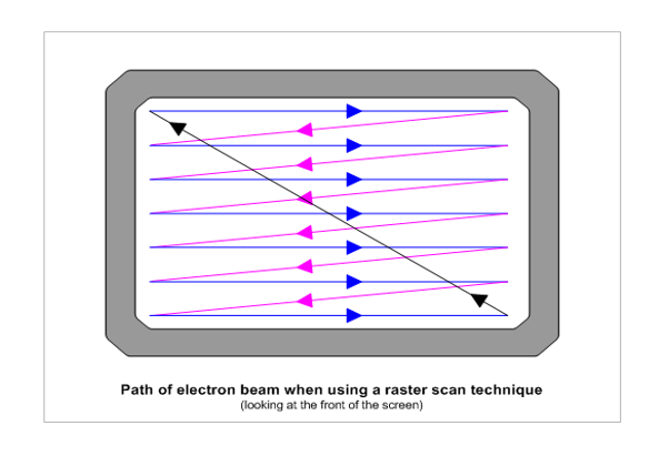
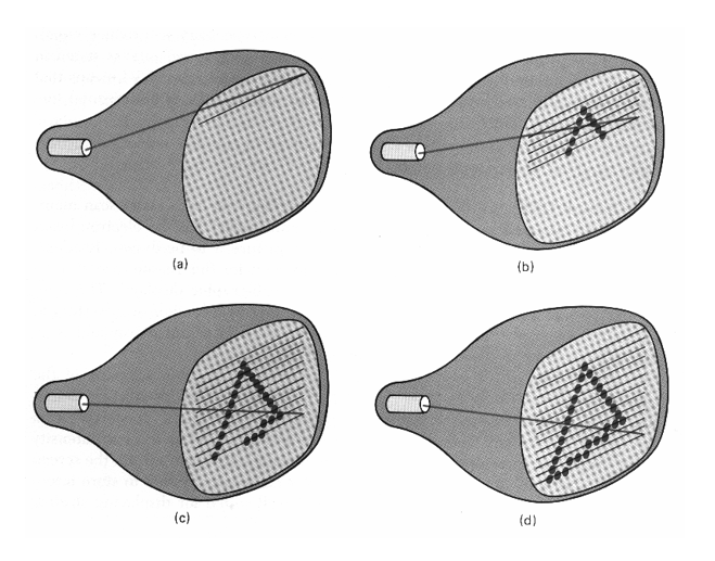
2. Raster Scan
- How it draws: The beam scans the entire screen row by row, from left to right and top to bottom. It turns on only where the image exists.
- Refresh needed? Yes – the whole screen is refreshed 60-70 times per second.
- Resolution: Medium – depends on the number of pixels.
- Flicker: High – due to constant refreshing.
- Animation ability: Strong – perfect for video, games, and moving images.
- Used in: Modern TVs, computer monitors, smartphones – the most common technique today.
Interlaced Scanning System
Interlaced scanning is a technique used in older Raster-Scan displays (like CRT TVs and monitors). It was developed to reduce screen flicker without increasing hardware costs or using extra data bandwidth.
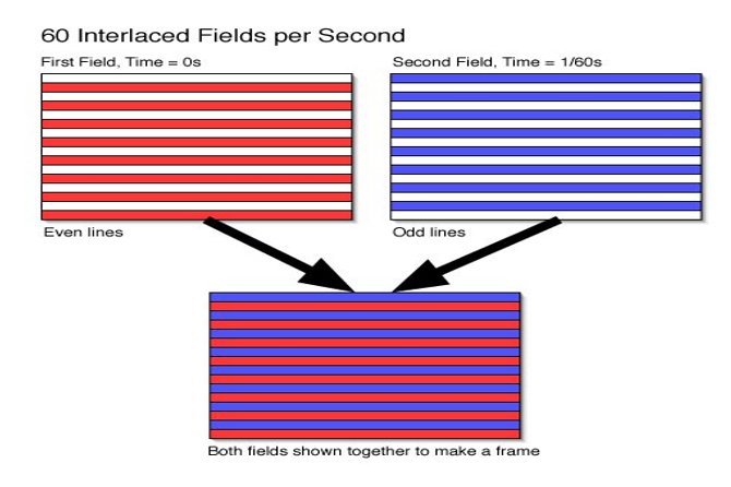
How It Works:
Instead of drawing an entire image frame from top to bottom in one go, the system splits it into two separate passes, called “fields.”
Step 1 (Odd Field): The electron beam scans only the odd-numbered lines (1, 3, 5, 7, …) across the screen.
Step 2 (Even Field): The beam returns to the top and scans the even-numbered lines (2, 4, 6, 8, …) to fill in the gaps.
These two fields are displayed alternately at high speed – typically 60 times per second (60Hz). The human eye and brain cannot detect this rapid switching, so they merge both fields into a single, smooth, flicker-free image.
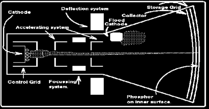
3. Direct View Storage Tube (DVST)
- How it draws: Uses two electron guns. One draws the image, the other stores it so it stays on screen without refreshing.
- Refresh needed? No – once drawn, the image stays for hours.
- Resolution: Good, but slightly blurry.
- Flicker: None at all – the image is completely stable.
- Animation ability: Very weak – to update even a small part, the whole screen must be erased and redrawn.
- Used in: Old terminals, radar displays, oscilloscopes.
Real-World example:
| Technique | Where You’ve Seen It |
|---|---|
| Random Scan | Old arcade games (Asteroids), Oscilloscopes, CAD monitors |
| Raster Scan | Every modern TV, smartphone, computer monitor, movie screen |
| DVST | Old radar screens, vintage lab oscilloscopes, old terminals |
1.4 CRT Display – Advantages and Disadvantages
Advantages:
Higher Resolution – CRT monitors can produce very sharp and detailed images with smooth lines and curves.
Wide Viewing Angle – You can view the screen from almost any angle without losing image quality, which is better than most other display technologies.
Low Cost – CRT displays are cheaper to manufacture compared to LCD, LED, or Plasma displays.
Disadvantages:
Thick and Bulky – CRT monitors are much larger and heavier than modern flat-panel displays.
Not Suitable for Small Devices – They cannot be used in portable or compact devices like watches, calculators, or smartphones because of their size and power requirements.
Viewable Area is Smaller – The actual screen size you see is slightly less than the monitor’s advertised size (e.g., a 17-inch CRT has a viewable area of about 15–16 inches).
Fragile and Heavy – CRTs are made of glass and are easily damaged. They are also very heavy, making them difficult to move or transport.
2. Flat Panel Displays
Flat-panel displays are a class of display devices that are significantly smaller in volume, lighter in weight, and consume less power compared to traditional CRT (Cathode Ray Tube) displays.Flat-panel displays are mainly divided into two types:
1. Emissive Displays
Emissive displays are devices that convert electrical energy directly into light.
Examples:
- Plasma Display Panels (PDP)
- Light Emitting Diodes (LED)
2. Non-Emissive Displays
Non-emissive displays use optical effects of light. They do not produce light themselves; instead, they utilize external light sources (such as sunlight or ambient light) to create graphic patterns.
Example:
- Liquid Crystal Displays (LCD)
2.1 Liquid Crystal Display(LCD)
is the core component of a display where the image is actually formed. It is a thin, flat glass layer
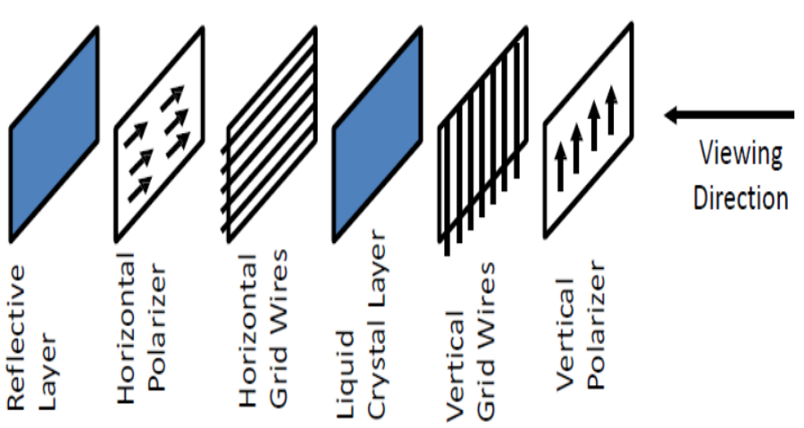
2.1.1 It has six layers that are
Reflective Layer reflects light.
Horizontal Polarizer makes the light horizontal.
Horizontal Grid Wires select rows.
Liquid Crystal Layer twists or blocks the light.
Vertical Grid Wires select columns.
Vertical Polarizer makes the light vertical.
Viewing Direction is the viewer’s direction.
2.1.2 How LCD Works
2.1.2.1 Light Path in a Reflective LCD
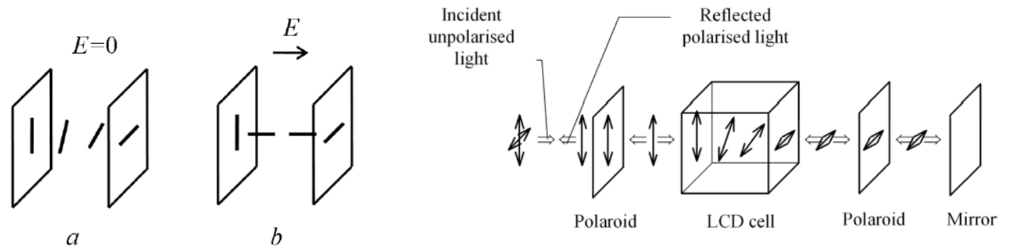
This is a Reflective LCD – where external light is used and light is reflected through a mirror.
| Step | What Happens |
|---|---|
| 1. Light Enters | External light (sunlight / room light) enters the LCD |
| 2. First Polarization | The polaroid polarizes the light |
| 3. Liquid Crystal Action | Liquid crystals twist or keep the light straight according to voltage |
| 4. Second Polarization | The second polaroid blocks or passes the light |
| 5. Reflection | The Mirror reflects the light back |
| 6. Viewing | The reflected polarized light reaches the viewer’s eye |
Reflective LCD (with Mirror):
External Light → Polaroid → LCD Cell → Polaroid → Mirror → (returns) → Polaroid → LCD Cell → Polaroid → Eye
2.1.2.2 A Transmissive LCD
This is a Transmissive LCD – where a backlight is used and light passes through the LCD once.
| Step | What Happens |
|---|---|
| 1. Light Enters | The Backlight (light from behind) enters the LCD |
| 2. Polarization | The first polarizer aligns the light in a specific direction |
| 3. Liquid Crystal Action | Liquid crystals twist or keep the light straight according to voltage |
| 4. Second Polarization | The second polarizer blocks or passes the light |
| 5. Color Creation | The color filter (if present) turns the light into red/green/blue |
| 6. Viewing | The image reaches the viewer’s eye |
Transmissive LCD (with Backlight):
Backlight → Polarizer → LCD Cell → Polarizer → Color Filter → Eye
Differences:
| Aspect | Reflective LCD (First Info) | Transmissive LCD (Second Info) |
|---|---|---|
| Light Source | External light (sun/room light) | Backlight (light from behind) |
| Reflector | Mirror is present | No mirror |
| Light Path | Twice (go and return) | Once (straight through) |
| Use in Dark | Not possible | Possible (due to backlight) |
| Examples | Calculators, Digital watches | Computer monitors, TVs, Mobiles |
| Power Consumption | Very low (no backlight) | Comparatively higher |
2.1.3 Types of Monitors (Based on the Diagram)
MONITORS
├── LCD Monitors (with Backlight)
│   ├── CCFL-backlit LCD (older)
│   └── LED-backlit LCD (modern)
└── OLED Monitors (No Backlight)
    └── Each pixel emits its own light
2.1.4 Light Sources in LCD
LCD is a non-emissive display – it does not produce light on its own, so it requires an external light source.
| Type | Light Source | Examples |
|---|---|---|
| Transmissive | Backlight from behind (LED/CCFL) | Monitors, TVs, Mobiles |
| Reflective | Ambient light (sun/room light) | Digital watches, Calculators |
| Transflective | Both backlight + ambient light | Smartwatches, Old PDAs |
2.1.5 The Market Reality
There is no separate product category called “LCD Display” in today’s market. Everything sold as “LCD” is actually an LCD Panel + Backlight combination.
How Displays Are Sold in the Market:
| Market Name | What It Actually Is | Backlight |
|---|---|---|
| LED Monitor / LED TV | LCD Panel + LED Backlight | LED |
| LCD Monitor / LCD TV (old) | LCD Panel + CCFL Backlight | CCFL |
| OLED TV / OLED Monitor | OLED Panel (no backlight) | None |
| QLED TV | LCD Panel + Quantum Dot + LED Backlight | LED |
Why Isn’t There a Separate “LCD Display” in the Market?
Backlight technology now determines the market name!
- When CCFL backlight was used → called “LCD TV”
- When LED backlight arrived → started calling it “LED TV”
2.1.6 Advantages of LCD
Low Power Consumption – An LCD cell consumes microwatts of power, which is thousands of times less than LED displays.
Operates at Low Voltage – Can work at voltages as low as 2 to 3 volts.
Easy to Control – Can be easily driven by MOS IC drivers.
Thin and Lightweight – Suitable for portable devices.
2.1.7 Limitations of LCD
Not Visible in the Dark – Requires a backlight or external light source.
Limited Viewing Angle – The image becomes unclear when viewed from extreme angles.
Limited Temperature Range – Performance degrades in extreme heat or cold.
3 TFT (Thin Film Transistor) Technology and TFT-LCD Display
3.1 What is TFT Technology?
TFT (Thin Film Transistor) is a special type of field-effect transistor that is manufactured using thin films. It is created by depositing thin layers of metallic connections, semiconductor active layers, and insulating layers.
TFT-LCD is an advanced version of LCD that uses TFT technology to improve image quality. It is a type of active matrix LCD
3.2 Real Examples
| Device | What It Actually Contains |
|---|---|
| TFT-LCD Monitor | TFT + LCD + Backlight |
| TFT-LCD TV | TFT + LCD + Backlight |
| Only TFT | Does not exist (cannot create a functional display on its own) |
3.3 Why is TFT Needed?
In regular LCDs (like calculators):
Voltage is applied directly to each segment
Applying voltage to one segment does not affect other segments
Problem with Large Displays:
- Large displays contain millions of pixels
- Providing separate connections for each pixel would require millions of connections
- Each pixel needs separate connections for three colors (red, green, blue)
Solution:
- Pixels are arranged in Rows and Columns
- This reduces the number of connections from millions to thousands
- Each pixel is given its own transistor switch
- This allows independent control of each pixel
3.4 Construction of TFT
Components:
- TFT is a Metal-Insulator-Semiconductor Field Effect Transistor
- Typically used as a Bottom-gate configuration
- ITO (Indium Tin Oxide) is used as electrodes
- Amorphous Silicon (a-Si:H) is used as the semiconductor
- a-Si has a lower bandgap than crystalline silicon (1.12 eV)
Each Pixel:
- A small capacitor consisting of:
- A transparent ITO layer at the front
- A transparent ITO layer at the back
- An insulating liquid crystal layer in between
Pixel Control:
- All pixels in a row receive positive voltage
- All pixels in a column receive negative voltage
3.5 Layers of TFT (Based on Diagram)
| Layer | Function |
|---|---|
| Polarizer | Polarizes the light |
| Color Filter | Creates colors (red/green/blue) |
| Black Matrix | Prevents light leakage between pixels |
| Common Electrode (ITO) | Common electrode for all pixels |
| Alignment Layer | Aligns liquid crystal molecules |
| Liquid Crystal | Twists or blocks light |
| Spacer | Maintains distance between layers |
| TFT-Array | Array of transistors |
| Pixel Electrode (ITO) | Electrode for each pixel |
| Backplane | Back supporting layer |
| Seal | Prevents liquid crystal from leaking out |
| Bonding PAD | Pads for external connections |
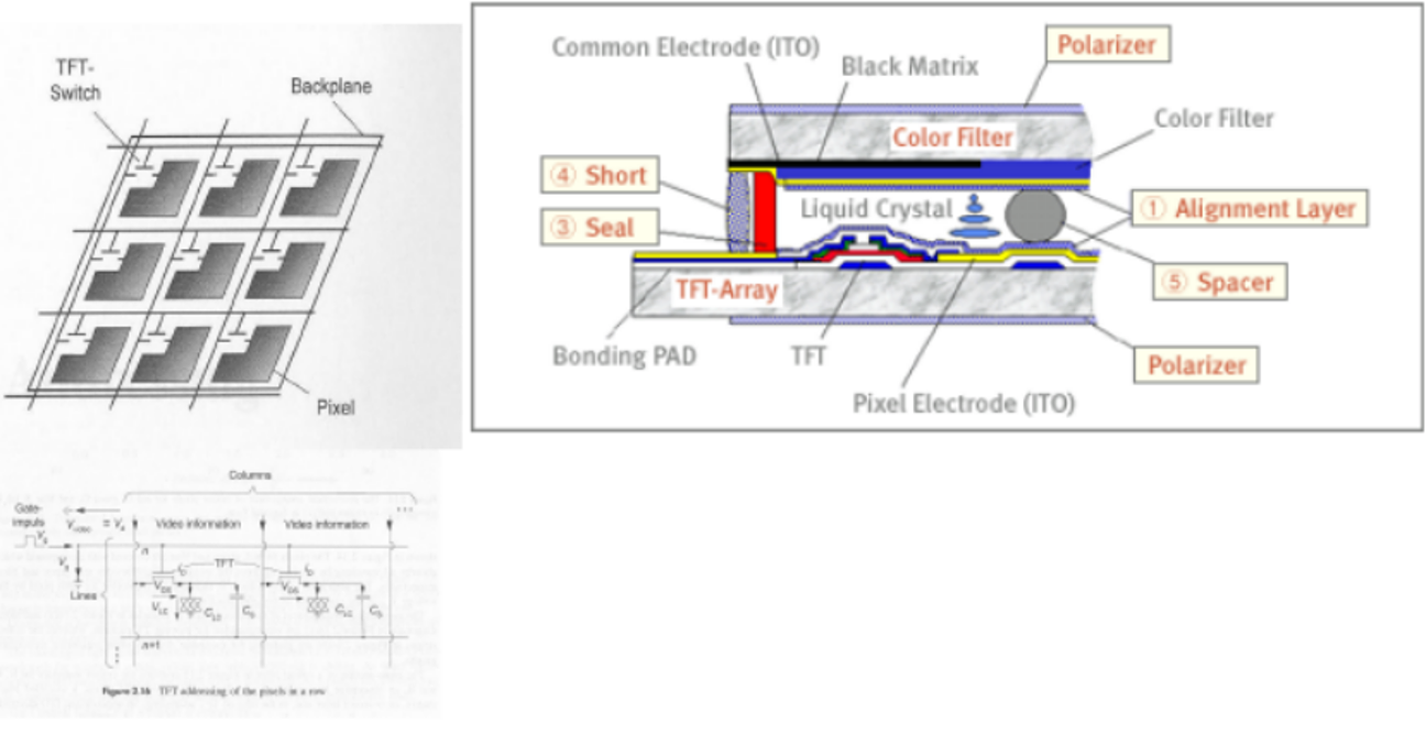
3.6 How TFT Works
Step 1: Light – The backlight creates white light.
Step 2: Polarization – The first polarizer aligns the light.
Step 3: TFT Activation – Rows and columns are selected and voltage is applied.
Step 4: Liquid Crystal – The liquid crystal twists or keeps the light straight according to the voltage.
Step 5: Second Polarization – The second polarizer blocks or passes the light.
Step 6: Color Creation – The color filter turns the light into red, green, or blue.
Step 7: Viewing – The image reaches the viewer’s eye.
3.7 Advantages of TFT
| Advantage | Explanation |
|---|---|
| High Resolution | Each pixel can be controlled individually |
| Fast Refresh | Can display fast-moving images smoothly |
| Low Cross-talk | One pixel’s signal does not affect others |
| Large Displays Possible | Can control millions of pixels |
| Better Image Quality | Improved contrast and color accuracy |
3.8 Disadvantages of TN TFT Displays
Limited Viewing Angles – The display suffers from poor viewing angles, especially in the vertical direction. Colors and contrast shift when viewed from above or below.
Limited Color Reproduction – They cannot display the full 16.7 million colors (24-bit true color) that modern graphics cards support. This results in less accurate and less vibrant colors compared to IPS or VA panels.
3.9 Applications of TFT
- Flat Panel Displays (monitors, TVs)
- Projectors
- Laptop Screens
- Smartphone Displays
- Tablets
- Digital Camera Viewfinders
4 Plasma Display Panel (PDP that is flat panel Emissive Display)
A Plasma Display Panel (PDP) is a type of flat panel display that is primarily used in large-screen TVs (typically 37 inches or larger).It uses gas to create images – similar to how fluorescent lamps or neon lights work.
4.2 Construction of a Plasma Display
A plasma display is made up of the following components:
| Component | Description |
|---|---|
| Glass Plates | Everything is arranged between two glass plates |
| Small Cells | Millions of tiny cells are placed between the glass plates |
| Gas | Each cell is filled with xenon and neon gas |
| Electrodes | Long electrodes are arranged in front of and behind each cell |
| Magnesium Oxide Layer | The cells are coated with a protective layer of magnesium oxide |
4.3. Working Principle of a Plasma Display
Step 1: Electrodes are Charged
- The control circuitry charges the electrodes.
- A voltage difference is created between the front and rear electrodes.
Step 2: Gas is Ionized (Plasma is Created)
- The voltage causes the gas inside the cell to ionize.
- The gas is converted into plasma.
- Plasma is ionized gas – where electrons and ions separate.
Step 3: Photons are Emitted
- Gas ions rush toward the electrodes and collide.
- This collision emits ultraviolet (UV) photons.
- Human eyes cannot see UV light, but it excites the phosphor.
Step 4: Color is Created
- Each cell has a phosphor coating at the back.
- UV photons excite the phosphor.
- The phosphor emits red, green, or blue light.
- The three colors mix to create a full-color image.
4.4 Plasma Display Characteristics
| Feature | Description |
|---|---|
| Thickness | Display panel is only 6 cm (2.5 inches) thick |
| Total Thickness | Less than 10 cm |
| Size | Can go up to 103 inches (262 cm) |
| Power Consumption | Higher for bright scenes (e.g., football matches) |
| Lifespan | Approximately 60,000 hours (about 7 years at 8 hours/day) |
4.5. Advantages of Plasma Display
| Advantage | Description |
|---|---|
| Large Displays | Can produce displays up to 103 inches |
| Thin | Thickness less than 10 cm – can be wall-mounted |
| Fast Response Time | Great for displaying fast-moving images |
| Wide Color Range | Vivid and clear colors |
| Wide Viewing Angle | Image stays clear even from extreme angles |
4.6. Disadvantages of Plasma Display
| Disadvantage | Description |
|---|---|
| Expensive | Much more costly than CRT or LCD |
| Burn-in Issue | Static images (like channel logos) can cause permanent marks on the screen |
| Unsuitable for Computer Monitors | Due to burn-in, cannot be used as a computer monitor or gaming display |
| High Power Consumption | Consumes a lot of power for bright scenes |
4.7. Plasma vs. Other Displays
| Feature | Plasma | LCD | OLED |
|---|---|---|---|
| Size | Large (37-103 inches) | Any size | Any size |
| Thickness | Less than 10 cm | Very thin | Extremely thin |
| Price | Expensive | Cheaper | Very expensive |
| Burn-in | Yes | No | Yes (minor) |
| Power Consumption | High | Low | Very low |
| Color Depth | Excellent | Good | Excellent |
| Viewing Angle | Wide | Limited | Wide |
4.8. Current Status of Plasma Displays
Plasma displays are no longer manufactured!
- Production of plasma TVs stopped around 2014.
- Reason: OLED and advanced LCDs (QLED, Mini-LED) became cheaper and better.
- Today, plasma TVs are only available in second-hand markets.