Mechanism of Optical Feedback
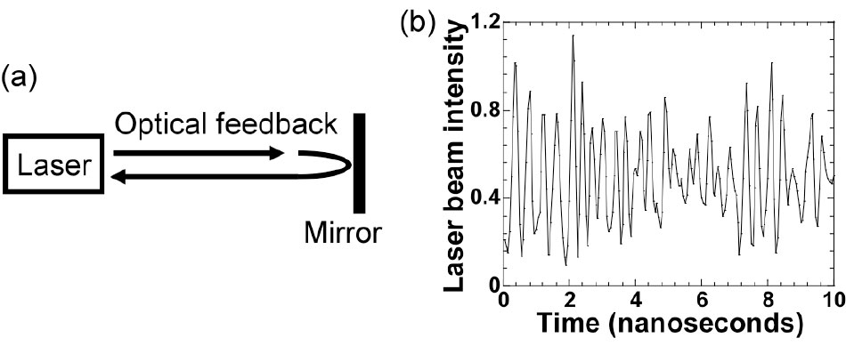
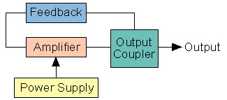
To create a LASER, simply generating light is not enough; that light must be amplified and made stronger. When light of a specific wavelength hits a mirror and is reflected back toward its own source, it is called Optical Feedback.
The Laser Procedure:
1. Cavity (The Optical Trap)
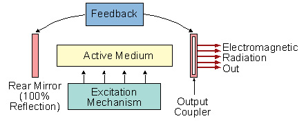
The Cavity is the “house” or container of the laser. It contains two mirrors that prevent light from escaping and keep it trapped inside the system.
2. Optical Feedback (Repeated Reflection)
The mirrors reflect the light back and forth like a “ping-pong” ball. Without this feedback mechanism, the light would never have the opportunity to gain enough strength to become a laser.
3. Stimulated Emission (Power Amplification)
When the reflected light hits excited atoms inside the Active Medium, those atoms release new light particles (Photons). These new photons are identical to the original ones, causing the light’s power to multiply rapidly.
4. Oscillation (Steady State)
During reflection within the cavity, some light is naturally lost. However, when the energy of the newly created light (Gain) becomes equal to or greater than the light being lost, the system reaches a powerful and stable state called Oscillation. At this exact moment, a bright, concentrated laser beam is emitted.
How it Works
A laser essentially contains two mirrors inside its structure:
- Full Mirror (High Reflector): This is located at one end and reflects 100% of the light back into the system.
- Partial Mirror (Output Coupler): This is located at the other end. It reflects most of the light back to keep the reaction going but allows a small percentage of light to escape—which is what we see as the Laser Beam.
Spectral Output
Spectral output is defined as intensity of light at each wavelength over the range of wavelengths emitted by the lamp.
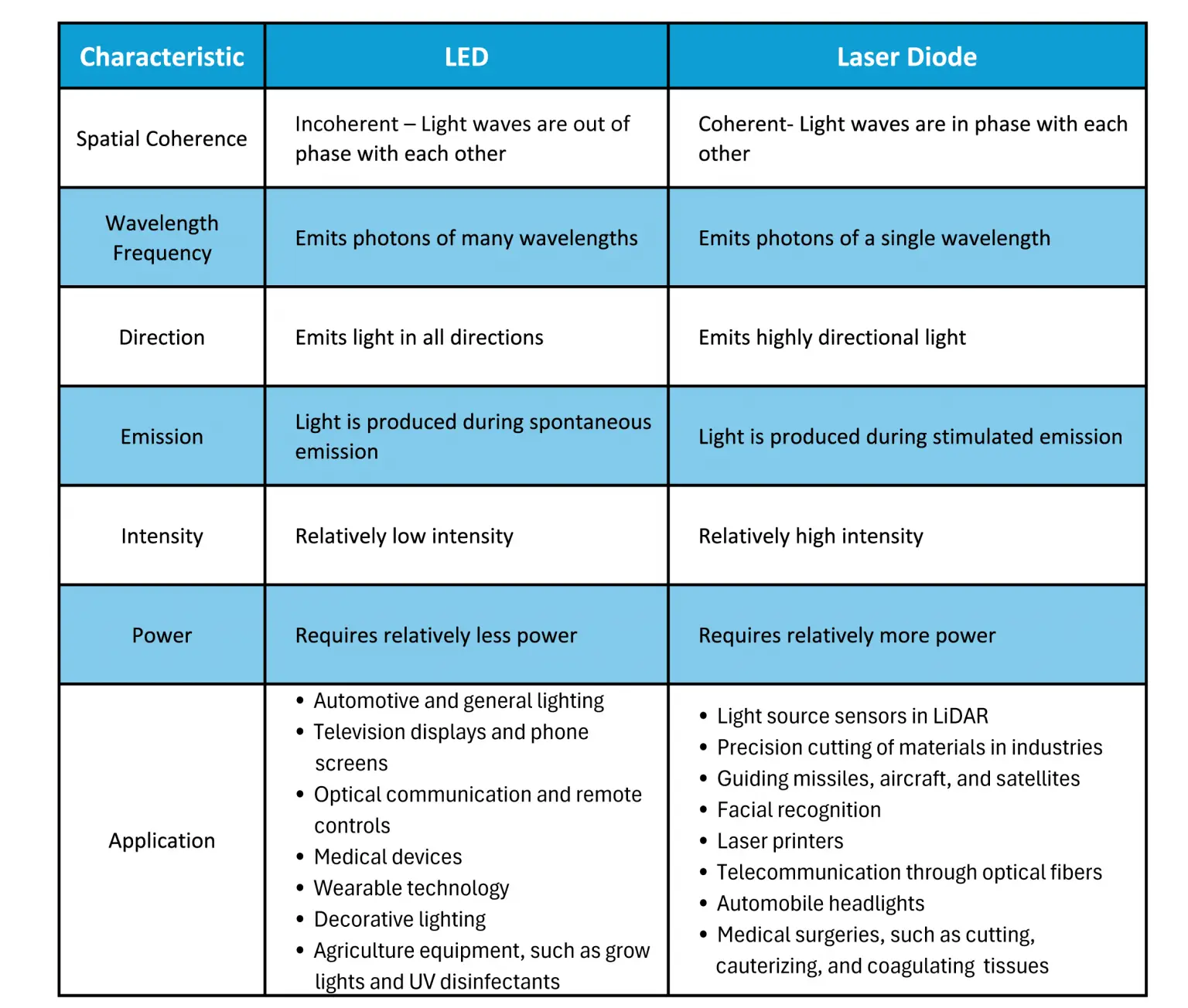
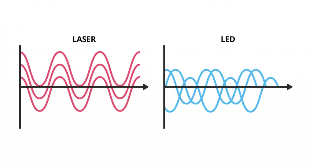
Quick Comparison
| Feature | LED Light | Laser Light |
|---|---|---|
| Output Type | Broad (Many colors/wavelengths) | Narrow (Single, precise color) |
| Mechanism | Simple spontaneous emission | Controlled optical feedback |
| Coherence | Low (Light spreads out) | High (Light stays in a tight beam) |
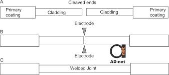
Fusion Splicing
is a high-precision technique used to join two optical fibers permanently by using localized heat (typically from an electric arc) to melt the glass ends together. Once the glass melts, the two fibers become a single, continuous strand.
Advantages (The Good)
- Best Performance: It has the lowest signal loss ($< 0.1$ dB) because the fibers are welded into one piece.
- Strong & Stable: The joint is very tough and isn’t affected by heat or cold.
- No Echoes: Since there is no gap between the glasses, light doesn’t bounce back (no back-reflection).
Drawbacks (The Bad)
- Expensive: You need a specialized, high-cost machine called a Fusion Splicer.
- Fragile: The glass becomes brittle once the coating is removed.
- Needs Protection: You must immediately add a Protection Sleeve to prevent the joint from snapping.
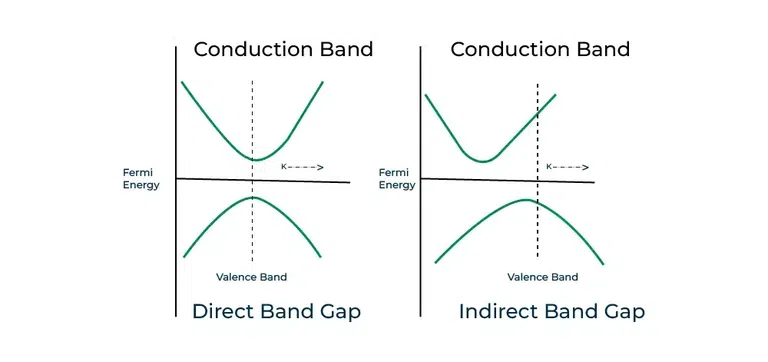
Direct and Indirect Band Gap.
Direct Band Gap — “The Source of Light”
- Core Concept: In these materials, when an electron drops from the upper level (Conduction Band) to the lower level (Valence Band), its horizontal position (Momentum) stays the same. It can drop straight down.
- Result: Because the transition is direct, almost all the released energy is converted into Light (Photons).
- Usage: These are essential for making LEDs and Lasers.
- Example: Gallium Arsenide (GaAs).
Indirect Band Gap — “The Source of Heat”
- Core Concept: In these materials, the electron cannot drop straight down. The top of the valence band and the bottom of the conduction band are “misaligned.” The electron must change its Momentum (shift left or right) to make the jump.
- Result: This extra shift requires an interaction with the crystal lattice (vibrations called Phonons), causing the energy to be released as Heat rather than light.
- Usage: These are poor for making light but excellent for Processors (CPUs) and Transistors.
- Example: Silicon (Si) and Germanium (Ge).
Comparison at a Glance:
| Feature | Direct Band Gap | Indirect Band Gap |
|---|---|---|
| Energy Emission | Primarily produces Light. | Primarily produces Heat. |
| Momentum ($k$) | No change (Vertical transition). | Changes (Diagonal transition). |
| Primary Use | Optical devices (LED, Laser). | Electronic devices (CPU, Transistor). |
| Example | Gallium Arsenide (GaAs) | Silicon (Si) |