Optical fiber cables designed
are to protect fragile fibers, maintain signal quality, and ensure mechanical strength.
Fiber Buffering
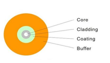
Buffering is the first layer of protection applied to the fiber to prevent microbending and physical damage.
Two Types of Buffering:
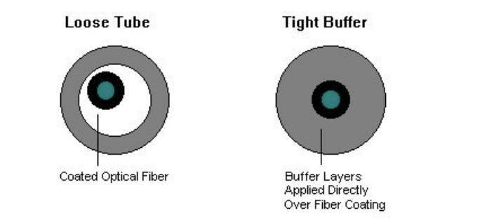
- Tight Buffering:
- Construction: A thick layer of plastic (like PVC) is applied directly over the fiber coating.
- Usage: Best for Indoor Cables or patch cords. It makes the cable very flexible and easy to handle in tight spaces.
- Loose-Tube Buffering:
- Construction: Fibers sit loosely inside a rugged plastic tube. This tube is usually filled with a water-resistant gel to prevent moisture buildup.
- Usage: Ideal for Outdoor or underground trunk lines. It allows the fiber to expand or contract during temperature changes without breaking.
Comparison Table: Tight vs. Loose-Tube Buffering
| Feature | Tight Buffering | Loose-Tube Buffering |
|---|---|---|
| Construction | Plastic layer is applied directly over the fiber coating. | Fibers sit loosely inside a rugged plastic tube. |
| Protection | Protects mainly against mechanical crush and physical impact. | Protects against moisture, water, and extreme temperature changes. |
| Water Resistance | No special protection against water. | Filled with water-resistant gel to block moisture. |
| Usage | Best for Indoor applications (Patch cords, office wiring). | Ideal for Outdoor, underground, or long-distance trunk lines. |
| Handling | Very flexible and easy to install connectors. | Harder to handle due to the messy gel inside the tube. |
Cable Strength and Structural Members
The components used to protect optical fiber cables from mechanical damage are known as Cable Strength and Structural Members.Since glass fibers are fragile, Strength Members are added so the cable can withstand pulling forces during installation and pressure when buried.
Key Components:
- Central Strength Member:
- A solid rod located at the very center of the cable, made of steel or fiberglass (FRP).
- Function: It provides rigidity and keeps the cable from buckling or collapsing.
- Aramid Yarns (Kevlar):
- Strong synthetic threads wrapped around the buffer tubes.
- Function: It provides high tensile strength, allowing the cable to be pulled through long conduits without snapping the fibers inside.
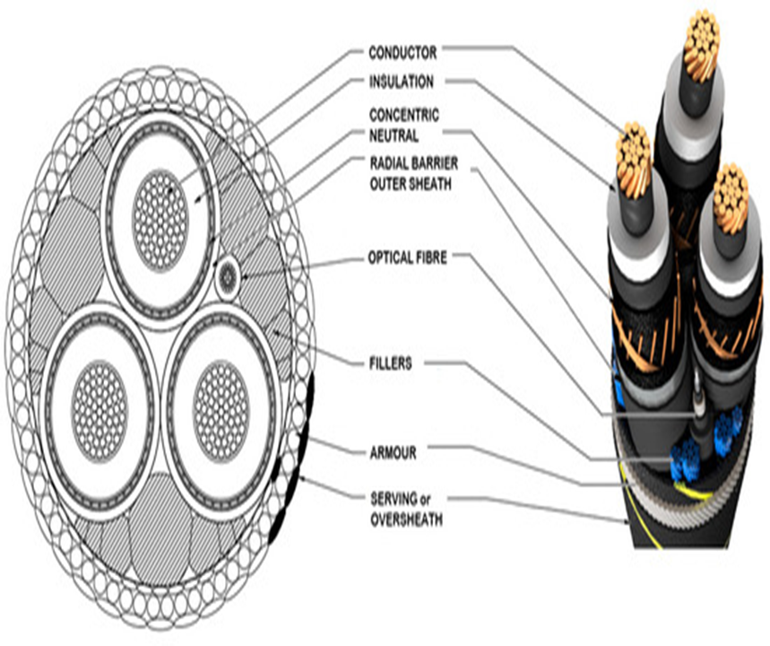
- Armor:
- A layer of corrugated steel or heavy-duty metal used in harsh environments or submarine (undersea) cables.
- Function: Protects the cable from high pressure, crushing forces, and even rodent bites.
Armour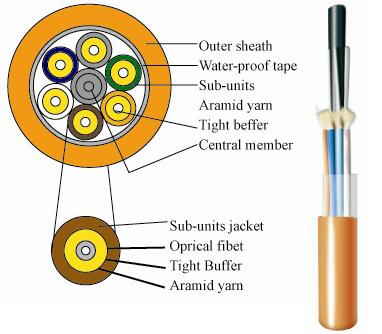
1. DFB Laser vs. Fabry–Pérot (FP) Laser
The main difference between these two lasers is how they control the “color” or wavelength of the light they produce.
FP Laser (The “Multi-Tone” Laser)
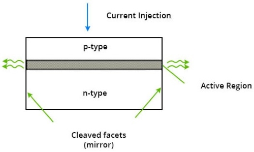
- Structure: It uses two simple mirrors at each end of the laser cavity. Light bounces back and forth between these mirrors.
- The Issue: Because the mirrors are simple, they allow multiple “modes” or colors of light to exit at once. This creates a broad beam.
- Result: Over long distances, this causes dispersion (the signal spreads out), making it unsuitable for high-speed, long-distance internet.
Armour
DFB Laser (The “Single-Tone” Laser)
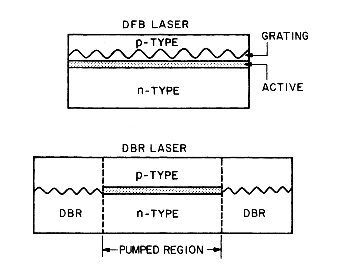
- Structure: Instead of simple mirrors, a Bragg Grating / filter (a series of microscopic ridges) is etched directly into the semiconductor.
- The Advantage: This grating acts like a super-fine filter that only allows one precise wavelength to escape.
- Use Case: Because it produces a “pure” single color, it is the standard for high-speed WDM systems.
Armour
| Feature | FP Laser | DFB Laser |
|---|---|---|
| Inside | Just two mirrors. | A “filter” (grating) inside. |
| Light | Messy (Multiple colors/wavelengths). | Clean (One single color/wavelength). |
| Distance | Short (Light blurs over long distances). | Long (Light stays sharp and clear). |
| Cost | Cheap. | Expensive. |
Fabrication of Fiber Couplers
Definition: A fiber coupler is a passive component used to either split an optical signal into multiple paths (Split) or combine multiple signals into a single fiber (Combine). The technical process of manufacturing these devices is known as Fabrication.
Primary Fabrication Methods
There are two main industrial methods used to fabricate these couplers:
1. Fused Biconical Taper (FBT) Method
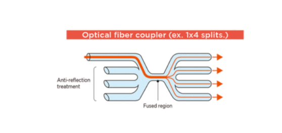
- Process: Two or more fibers are placed side-by-side, twisted together, and then heated using a flame or a laser. While the glass is molten, the fibers are stretched (tapered) from both ends.
- How it Works: As the fibers become thinner in the “tapered” region, the light in one fiber core begins to leak into the adjacent fiber core.
- Best For: Creating simple power splitters (e.g., 1x2, 1x4) where you need to divide the signal power equally (like a 50/50 split).
2. Polished Fiber Method
Polished Fiber Method
Process:
The fiber is placed into a groove in a glass block. Then, the outer layer or Cladding is polished down until it becomes so thin that the internal Core is almost exposed. Finally, two such blocks are joined together, one on top of the other.
How it Works:
When the two cores are brought extremely close to each other, light transfers from one core to the other through a process called Evanescent Wave Coupling.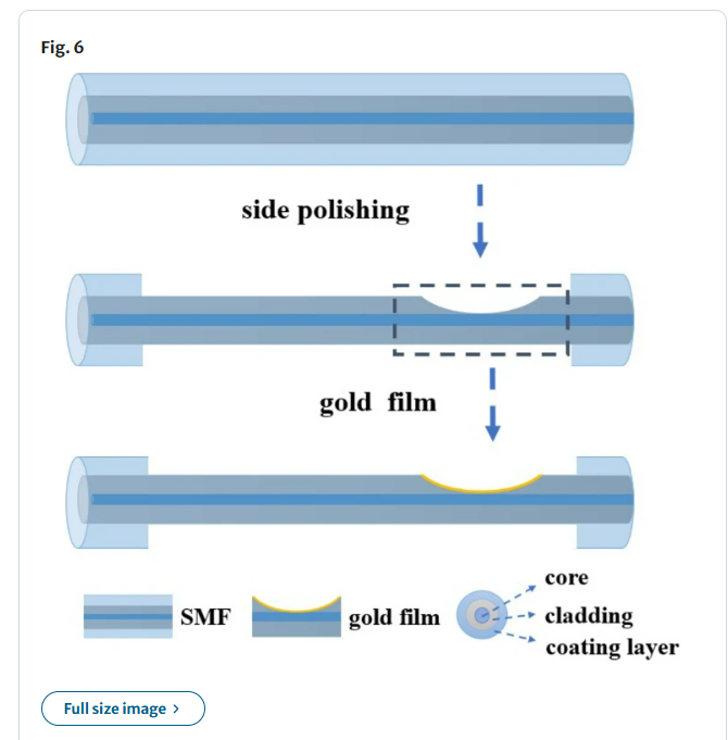
To divide water from a pipe, you would use a standard T-junction (FBT). However,
if you want to place a sensor on the pipe wall to test for germs inside the water,
you must grind the pipe wall down until it is thin (Polished).