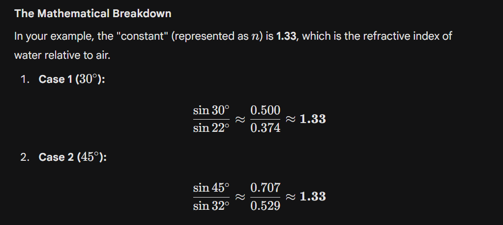
Snell’s law
is defined as follows: “For light of a given color and for a given pair of media, the ratio of the sine of the angle of incidence to the sine of the angle of refraction is a constant.”
The Critical Angle
Critical Angle($\theta_c$) can be described as the angle of incidence that offers an angle of refraction of 90 degrees.
What is the critical ray?
The critical ray (more commonly referred to as the critical angle) is the specific incident light ray that, when hitting the boundary between two materials, results in a refraction angle of exactly
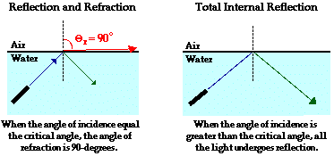
Fig. 2.6 & 2.7: “
Key Conditions for a Critical Angle:
Direction: Light must be traveling from a denser medium (like glass or water) toward a less dense medium (like air).
The Result: At exactly the critical angle, the light doesn’t exit into the air; instead, it skims along the surface at 90°.
Total internal reflection (TIR)
is the complete reflection of a light ray back into a denser medium (like glass or water) from the boundary with a less dense medium (like air)
Core: This is the center part of the cable where the light actually travels. It is a denser medium (High Refractive Index).
Cladding: This is the outer layer that surrounds the core. It is a lighter medium (Low Refractive Index).
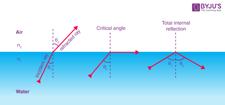
Fig. 2.6 & 2.7: “
How to send , transmitting and received data through optical fiber
1. Transmitter Stage (Creating and Sending the Signal)
As shown in the process begins here:
- Encoding: Your digital data (0s and 1s) is converted into a special code suitable for light transmission.
- Laser Drive Circuit: This circuit controls a semiconductor laser. It turns the laser on and off very rapidly according to the digital code.
- Laser Launch: These pulses of light are then “launched” into the opening of the fiber optic cable.
2. Transmission Stage (How Light Travels)
shows how the light moves through the cable:
- Core and Cladding: The cable has a high-index Core (center) and a low-index Cladding (outer layer).
- Total Internal Reflection (TIR): When light hits the boundary between the core and cladding at an angle greater than the Critical Angle ($\phi > \phi_c$), it cannot escape.
- Result: The light bounces off the walls like a mirror, staying trapped inside the core. It travels with 99.9% efficiency, meaning very little light is lost.
3. Receiver Stage (Catching and Converting the Signal)
At the other end, an APD (Avalanche Photodiode) is used to catch the light:
- APD Function: It is a super-sensitive detector. When a single photon (light particle) hits it, it triggers a “chain reaction” (Avalanche) to create many electrons. This turns even very faint light into a strong electrical signal.
- Amplifier & Equalizer: These parts clean up the signal. If the light pulses became “blurry” or weak during the long journey, the equalizer sharpens them back up.
- Decoder: Finally, the decoder turns the electrical pulses back into the original digital data (Output).
Why use an APD instead of a regular PIN diode?
An APD is much better for long distances because:
- It can detect extremely faint signals that a normal diode would miss.
- It has internal gain, meaning it automatically multiplies the signal strength.
- It is perfect for high-speed, long-distance communication where light gets weak.
Simple Direction:
Digital Data ->Laser Pulses -> Fiber Bouncing (TIR) -> APD Detection -> Digital Data.
Acceptance Angle
($\theta_a$)In simple words, the Acceptance Angle is the maximum angle at which a light ray can enter the optical fiber and stay trapped inside to travel forward.
Light passin through optical fiber
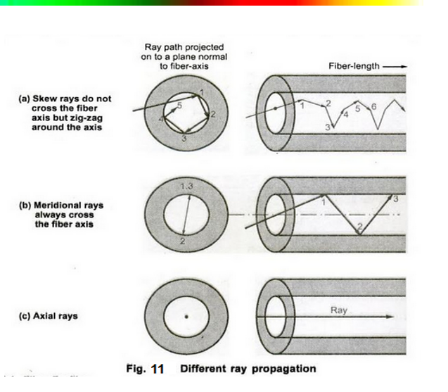
Fig. 2.6 & 2.7: “Lets” vs. “Let’s”: The Right Way to Use Each Word
- Axial Rays These are the simplest rays. They travel straight down the center of the fiber core without hitting the walls.
Path: A straight line along the fiber axis.
Speed: This is the fastest path because it is the shortest distance.
- Meridional Rays These rays travel in a zig-zag pattern, constantly passing through the center (axis) of the fiber.
Path: They bounce off the core-cladding boundary using Total Internal Reflection and cross the center line every time they bounce.
Usage: Most simple physics diagrams of fiber optics show meridional rays to explain how light stays trapped.
- Skew Rays These are the most complex. They never cross the center axis of the fiber.
Path: Instead of a simple zig-zag, they travel in a helical (spiral) pattern around the core.
Visual: If you looked down the fiber, a skew ray would look like it is circling the center rather than going through it.
Note: Skew rays are generally harder to calculate mathematically but represent a large portion of the light in a “multimode” fiber.
Typical configuration of opitcal fiber
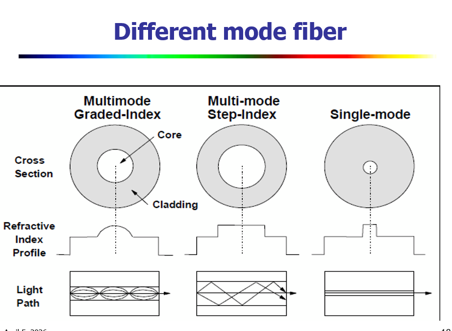
Fig. 2.6 & 2.7: “Lets” vs. “Let’s”: The Right Way to Use Each Word
1. Multi-mode Step-Index Fiber
- Construction: It has a large core. The refractive index is uniform throughout the core and changes abruptly at the cladding boundary.
- Light Path: Light travels in a “zig-zag” pattern, bouncing off the cladding.
- Problem: Because different rays take different paths (some longer, some shorter), they arrive at different times, causing high Modal Dispersion.
2. Multi-mode Graded-Index Fiber
- Construction: The core’s refractive index is highest at the center and decreases gradually toward the cladding (curved profile).
- Light Path: Light travels in a “sinusoidal” or curved wave pattern.
- Advantage: Even though rays take different paths, the rays near the edge travel faster (because the index is lower there). This allows all rays to arrive at the end at nearly the same time, reducing dispersion.
3. Single-mode Fiber
- Construction: It has an extremely thin core (about 8-10 micrometers).
- Light Path: Light travels in a straight line through the center. There is only one “mode” or path for the light.
- Advantage: Since there is only one path, there is zero Modal Dispersion. This makes it the best choice for long-distance and high-speed communication (like undersea cables or backbone networks).
Summary Table
| Type | Core Size | Dispersion | Distance |
|---|---|---|---|
| Step-Index | Large | High | Short |
| Graded-Index | Medium | Medium | Medium |
| Single-mode | Very Small | Very Low | Very Long |
Important Note some terms of words
- The core refractive index n1 is the measure of how fast light travels through the central, light-conducting region of an optical fiber
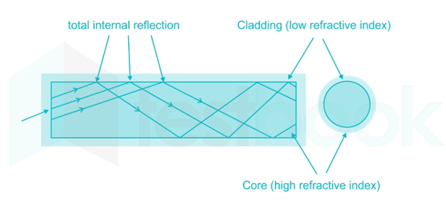
- The cladding refractive index n2 is the numerical value representing the optical density of the outer layer of an optical fiber
- Cladding is the lower-refractive-index material surrounding a fiber optic core, crucial for confining light within the core through total internal reflection.
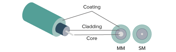
Relative Refractive Index Difference ($\Delta$): ১% বা $0.01$। This is the relative difference between the refractive index of the core and the cladding.
The core refractive index is the measure of how fast light travels through the central, light-conducting region of an optical fiber