Optical Fiber Communication
Here is the English version of the response, structured for clarity and academic use:
What is Optical Fiber?
An optical fiber is a flexible, ultra-thin strand of high-quality glass or plastic that transmits information as light pulses over long distances at high speeds
Typical Configuration of Optical Fiber
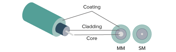
A standard optical fiber consists of three main concentric layers. Below is the description and a conceptual breakdown:
1. Core
- Description: The innermost layer of the fiber.
- Function: It is the actual medium through which light travels.
- Material: Made of high-quality glass or plastic with a high refractive index ($n_1$).
2. Cladding
- Description: The layer surrounding the core.
- Function: It keeps the light trapped inside the core by reflecting it back.
- Material: It has a slightly lower refractive index ($n_2$) than the core ($n_1 > n_2$). This difference in refractive index is what enables Total Internal Reflection.
3. Buffer Coating / Jacket
- Description: The outermost protective layer.
- Function: It does not play a role in light transmission but protects the glass from moisture, physical damage, abrasion, and environmental stress.
Link for optical fiber
Avalanche Photodiode
An Avalanche photodiode (APD) is a highly sensitive semiconductor detector that uses the photoelectric effect to convert optical signals into electrical signals. Here is the simple breakdown of how it works and why it’s special:
1. What makes it different?
- Conventional Photodiodes (PIN): These are like simple solar cells. One photon of light creates one electron. The resulting electrical signal is very weak and often needs an external amplifier.
- APD: It uses a process called Avalanche Breakdown. One photon hits the detector and triggers a “chain reaction,” creating a flood of electrons. This means a tiny bit of light produces a very large electrical current.
2. High Sensitivity
Because of this internal “multiplication” of electrons, the APD can detect faint or weak light signals that a normal photodiode would miss. This makes it perfect for long-distance fiber optic cables where the light gets dimmer as it travels.
3. Reach-Through Design
It is often called a “Reach-Through” APD because it is designed so that the internal electric field “reaches through” the entire light-sensitive area. This ensures that almost every photon hitting the device is caught and amplified efficiently.
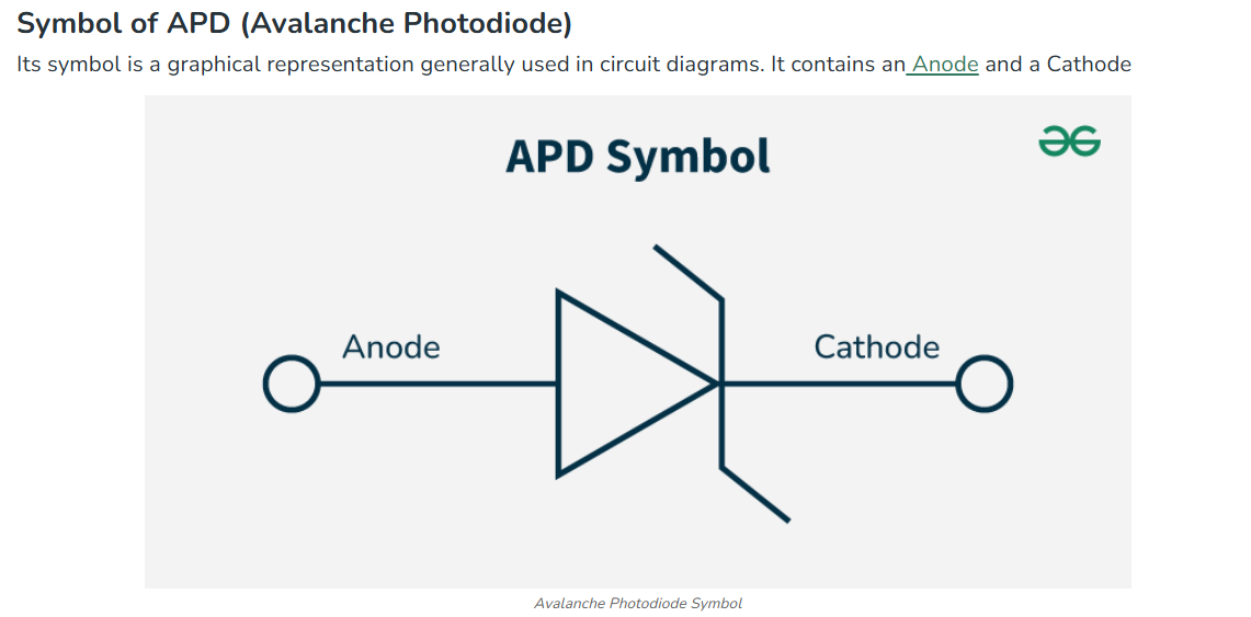
Fig. 2.6 & 2.7: “Lets” vs. “Let’s”: The Right Way to Use Each Word
What is Fiber Optic Cable?
Fiber optic cable is a high-speed networking technology that transmits data as pulses of light through thin strands of glass or plastic.
Here is a simple and easy-to-read breakdown of how Fiber Optic cables work, why they are great, and what their downsides are.
General system and optical fiber system
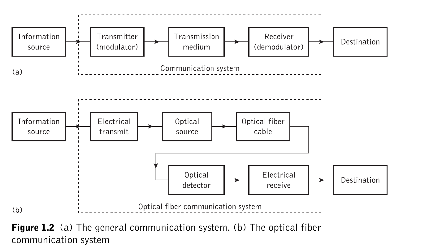
Fig. 2.6 & 2.7: “
1. Where do we use Fiber Optic Cables?
- Internet & Phones: They carry huge amounts of data over very long distances with almost no signal loss.
- TV (Cable TV): They deliver high-definition (HD) video and clear audio directly to your home.
- Data Centers: They are the “super-highways” that connect thousands of servers inside giant tech companies like Google or Facebook.
- Local Networks: Used in LANs and WANs to connect computers, routers, and switches at high speeds.
- Medicine: Doctors use them in Endoscopes (tiny cameras) to see inside the human body and in lasers for surgery.
2. The Advantages (Why Fiber is better than Copper)
- Speed & Bandwidth: Light is the fastest thing in the universe. Fiber can carry much more data than old copper wires.
- Long Distance: Signals can travel much further without losing strength (less power loss).
- No Interference: Since they use light, they aren’t affected by magnets or electricity (Electromagnetic Interference).
- Thin & Light: They are about 4.5 times smaller and much lighter than copper, making them easier to fit into tight spaces.
- Highly Secure: It is almost impossible to “hack” or tap into a fiber cable because it doesn’t leak electrical signals.
- Durable: They are flexible and can resist acidic elements that would normally damage copper.
3. The Disadvantages (The Challenges)
- High Cost: Producing the glass fiber is expensive. You also need special, high-priced equipment to install and test it.
- Fragile: Because they are made of glass, they are brittle. If you bend them too sharply, they will snap.
- Difficult Splicing: Connecting two fibers together is a very delicate “surgery.” If the join isn’t perfect, the signal will fail.
- Easy to Damage: Because they are so thin, they are easily cut by accident during road construction or building renovations.
Snell’s law
is defined as follows: “For light of a given color and for a given pair of media, the ratio of the sine of the angle of incidence to the sine of the angle of refraction is a constant.”
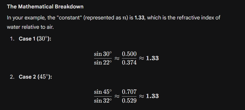
Fig. 2.6 & 2.7: “Lets” vs. “Let’s”: The Right Way to Use Each Word
The Critical Angle
is the specific “tipping point” angle of light that determines whether light passes through a surface or reflects back like a mirror and that results in an angle of refraction of 90.If the incidence angle exceeds this value, total internal reflection occurs.
What is the critical ray?
At a certain point, the critical angle, the ray of light will come up to the top of the glass surface and goes out along the glass surface. It doesn’t get into the air.
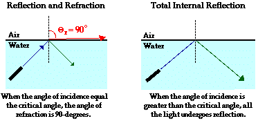
Fig. 2.6 & 2.7: “
Key Conditions for a Critical Angle:
Direction: Light must be traveling from a denser medium (like glass or water) toward a less dense medium (like air).
The Result: At exactly the critical angle, the light doesn’t exit into the air; instead, it skims along the surface at 90°.
Total internal reflection (TIR)[পূর্ণ অভ্যন্তরীণ প্রতিফলন]
is the complete reflection of a light ray back into a denser medium (like glass or water) from the boundary with a less dense medium (like air)
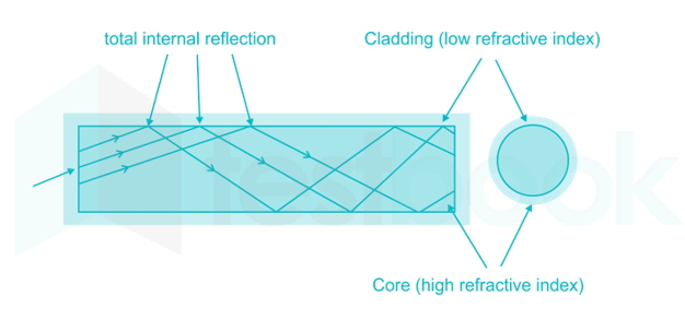
Core: This is the center part of the cable where the light actually travels. It is a denser medium (High Refractive Index).

Cladding: This is the outer layer that surrounds the core. It is a lighter medium (Low Refractive Index).
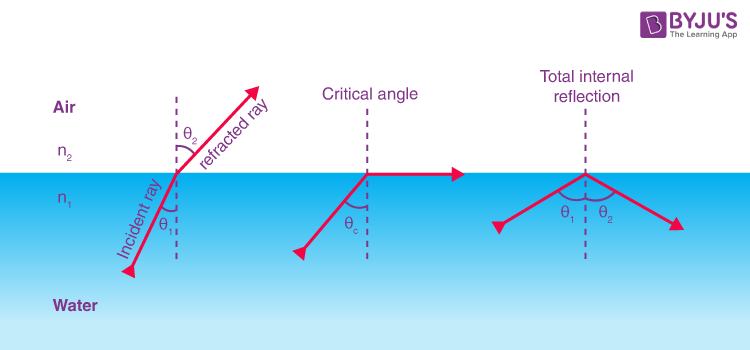
Fig. 2.6 & 2.7: “Lets” vs. “Let’s”: The Right Way to Use Each Word
How to send , transmitting and received data through optical fiber
1. Transmitter Stage (Creating and Sending the Signal)
As shown in the process begins here:
- Encoding: Your digital data (0s and 1s) is converted into a special code suitable for light transmission.
- Laser Drive Circuit: This circuit controls a semiconductor laser. It turns the laser on and off very rapidly according to the digital code.
- Laser Launch: These pulses of light are then “launched” into the opening of the fiber optic cable.
2. Transmission Stage (How Light Travels)
shows how the light moves through the cable:
- Core and Cladding: The cable has a high-index Core (center) and a low-index Cladding (outer layer).
- Total Internal Reflection (TIR): When light hits the boundary between the core and cladding at an angle greater than the Critical Angle ($\phi > \phi_c$), it cannot escape.
- Result: The light bounces off the walls like a mirror, staying trapped inside the core. It travels with 99.9% efficiency, meaning very little light is lost.
3. Receiver Stage (Catching and Converting the Signal)
At the other end, an APD (Avalanche Photodiode) is used to catch the light:
- APD Function: It is a super-sensitive detector. When a single photon (light particle) hits it, it triggers a “chain reaction” (Avalanche) to create many electrons. This turns even very faint light into a strong electrical signal.
- Amplifier & Equalizer: These parts clean up the signal. If the light pulses became “blurry” or weak during the long journey, the equalizer sharpens them back up.
- Decoder: Finally, the decoder turns the electrical pulses back into the original digital data (Output).
Why use an APD instead of a regular PIN diode?
An APD is much better for long distances because:
- It can detect extremely faint signals that a normal diode would miss.
- It has internal gain, meaning it automatically multiplies the signal strength.
- It is perfect for high-speed, long-distance communication where light gets weak.
Simple Direction:
Digital Data ->Laser Pulses -> Fiber Bouncing (TIR) -> APD Detection -> Digital Data.
Acceptance Angle
($\theta_a$)In simple words, the Acceptance Angle is the maximum angle at which a light ray can enter the optical fiber and stay trapped inside to travel forward.
Light passin through optical fiber
Fig. 2.6 & 2.7: “Lets” vs. “Let’s”: The Right Way to Use Each Word Fig. 2.6 & 2.7: “Lets” vs. “Let’s”: The Right Way to Use Each Word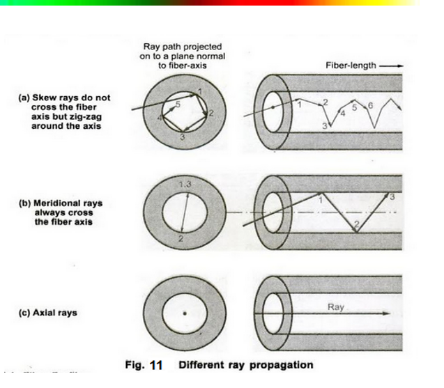
- Axial Rays These are the simplest rays. They travel straight down the center of the fiber core without hitting the walls.
Path: A straight line along the fiber axis.
Speed: This is the fastest path because it is the shortest distance.
- Meridional Rays These rays travel in a zig-zag pattern, constantly passing through the center (axis) of the fiber.
Path: They bounce off the core-cladding boundary using Total Internal Reflection and cross the center line every time they bounce.
Usage: Most simple physics diagrams of fiber optics show meridional rays to explain how light stays trapped.
- Skew Rays These are the most complex. They never cross the center axis of the fiber.
Path: Instead of a simple zig-zag, they travel in a helical (spiral) pattern around the core.
Visual: If you looked down the fiber, a skew ray would look like it is circling the center rather than going through it.
Note: Skew rays are generally harder to calculate mathematically but represent a large portion of the light in a “multimode” fiber.
Important Note some terms of words
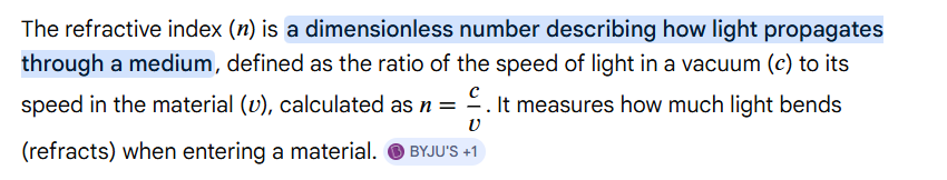
- The core refractive index n1 is the measure of how fast light travels through the central, light-conducting region of an optical fiber
- The cladding refractive index n2 is the numerical value representing the optical density of the outer layer of an optical fiber
- Cladding is the lower-refractive-index material surrounding a fiber optic core, crucial for confining light within the core through total internal reflection.
Relative Refractive Index Difference ($\Delta$): ১% বা $0.01$। This is the relative difference between the refractive index of the core and the cladding.
The core refractive index is the measure of how fast light travels through the central, light-conducting region of an optical fiber
Attenuation
in optical fiber is the reduction in signal strength (power) as light travels through the cable, measured in decibels (dB) per kilometer (dB/km). A decibel (dB) is a logarithmic unit used to measure the intensity or loudness of sound, as well as signal power in electronics.
What is Material Absorption?
In simple terms, material absorption is a loss mechanism where the glass (Silica) used to make the fiber absorbs some of the optical signal’s energy and converts it into heat. This results in the weakening of the signal (attenuation) as it travels through the fiber.
1. Intrinsic Absorption (Natural Loss) This occurs due to the inherent properties of the fiber’s core material (pure Silica).
- Cause: It happens when the glass molecules interact with light at specific wavelengths, causing the molecules to vibrate and absorb energy.
- Key Point: It is a fundamental characteristic of the material and cannot be completely avoided, even in a perfectly pure fiber.
2. Extrinsic Absorption (External Loss) This is caused by impurities or defects within the glass during the manufacturing process.
- Cause: If tiny amounts of metals (like iron, copper, or chromium) or water (OH⁻ ions/hydroxyl ions) remain inside the glass, they absorb a massive amount of light.
- The “Water Peak”: The OH⁻ ions are particularly notorious for causing high absorption at specific wavelengths (like 1380 nm).
- Modern Status: With advanced fabrication techniques, fibers are now so pure that extrinsic losses have been significantly reduced, allowing for high-efficiency long-distance communication.
Intrinsic Absorption (অভ্যন্তরীণ শোষণ):
UV শোষণ - সিলিকার Si-O বন্ধনের ইলেকট্রনিক শোষণ
IR শোষণ - Si-O বন্ধনের আণবিক কম্পন
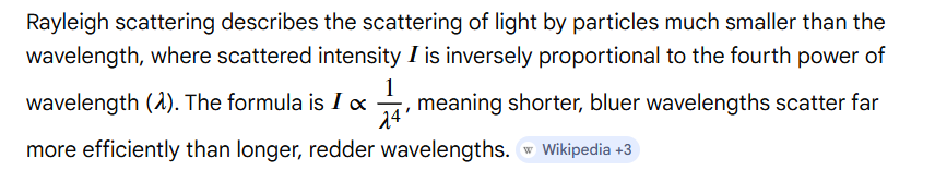
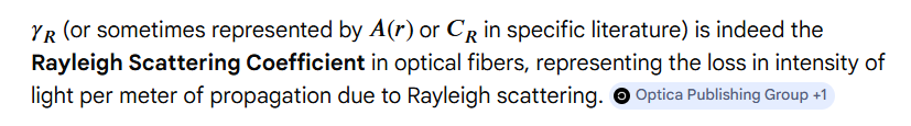
Rayleigh Scattering - কাচের অভ্যন্তরীণ কাঠামোগত ওঠানামা
Extrinsic Absorption (বহিরাগত শোষণ):
OH⁻ আয়ন শোষণ - উৎপাদনের সময় পানি দূষণ থেকে
Transition Metal Ion শোষণ - Fe, Cu, Cr, V ইত্যাদি অপদ্রব্য থেকে
What is Linear Scattering?
In simple terms, linear scattering occurs when light traveling through the fiber hits tiny particles or microscopic irregularities (inhomogeneities) within the glass. This causes the light to deviate from its original path and spread in different directions.
- Mode Transfer As a result of scattering, light traveling in a specific path (called a Mode) can change its direction and transfer into a different mode.
Analogy: It is like driving a car on a straight road and suddenly hitting a small stone, which causes the car to swerve into a different lane.
- Signal Attenuation (Loss) The biggest problem with scattering is that the redirected light often enters a path that the fiber cannot contain.
Leaky or Radiation Modes: The scattered light may hit the core-cladding boundary at an angle that does not allow for Total Internal Reflection.
Result: The light escapes from the core into the cladding and is eventually lost as radiation. This causes the optical signal to become weak (attenuated).
What is Dispersion?
In simple terms, dispersion refers to the distortion of the signal’s shape as it travels through the fiber. While Attenuation deals with the loss of power (signal strength), Dispersion deals with the spreading of light pulses over time.
What is Fiber Bend Loss?
In simple terms, when an optical fiber takes a sharp turn or bend along its path, some of the light energy escapes from the core into the cladding. This is also known as Radiation Loss.
The Main Reasons for this Loss:
The Evanescent Field: When light travels through the fiber core, a small portion of its energy actually penetrates slightly into the cladding. This part of the light is called the ‘Evanescent Field’.
The Limitation of the Speed of Light: To maintain a constant Wavefront (a straight line of light moving forward), the part of the light on the outside of the bend must travel much faster than the light on the inside of the bend.
Analogy: Think of a line of people holding hands and turning a corner; the person on the outside must run much faster to keep the line straight.
- Radiation (Escape of Energy): The problem arises when the light in the cladding (the evanescent field) is required to travel faster than the speed of light in that specific medium to keep up with the wavefront.
Since traveling faster than the speed of light in a medium is physically impossible, that part of the light can no longer be guided within the fiber.
Result: This energy is “thrown off” or radiated away from the fiber core, causing signal attenuation.
Block by windows


Refractive Index
Relay scattering
Gemini said
Rayleigh Scattering (রেলে বিচ্ছুরণ) হলো এমন একটি প্রক্রিয়া যেখানে আলোর তরঙ্গদৈর্ঘ্যের (Wavelength) তুলনায় অনেক ক্ষুদ্র কণা বা অণু (যেমন বাতাসের নাইট্রোজেন বা অক্সিজেন অণু) দ্বারা আলো চারদিকে ছড়িয়ে পড়ে।

সহজ কথায়: আলো যখন বাতাসের অতি ক্ষুদ্র কণার ওপর পড়ে, তখন সেটি সবদিকে ছিটিয়ে যায়। এই ছিটিয়ে যাওয়াকেই বিচ্ছুরণ বলে।
Numerical Aperatur
In optics, the numerical aperture (NA) of an optical system is a dimensionless number that characterizes the range of angles over which the system can accept or emit light
Critical radious carveture
It is the minimum bending radius of an optical fiber below which the light signal is no longer confined to the core by total internal reflection. If the fiber is bent beyond this radius, significant radiation losses (attenuation) occur as light leaks into the cladding.